3D Printing Article 2: How To Make Basic Items For Radio Yachting
Introduction
In this article I am going to assume that you know very little about 3D printing. If you have some idea then some of this will be a revision for you. Also, at this early stage I will avoid the confusing jargon that comes with this new technology and slowly introduce the more important terminology to you as the journey proceeds.
So what are we making today? I would like to start with a basic lightweight boom section to show you how easy it is to make RC yacht parts. This can be printed on even the most basic of printers.
Making a lightweight rectangular boom section

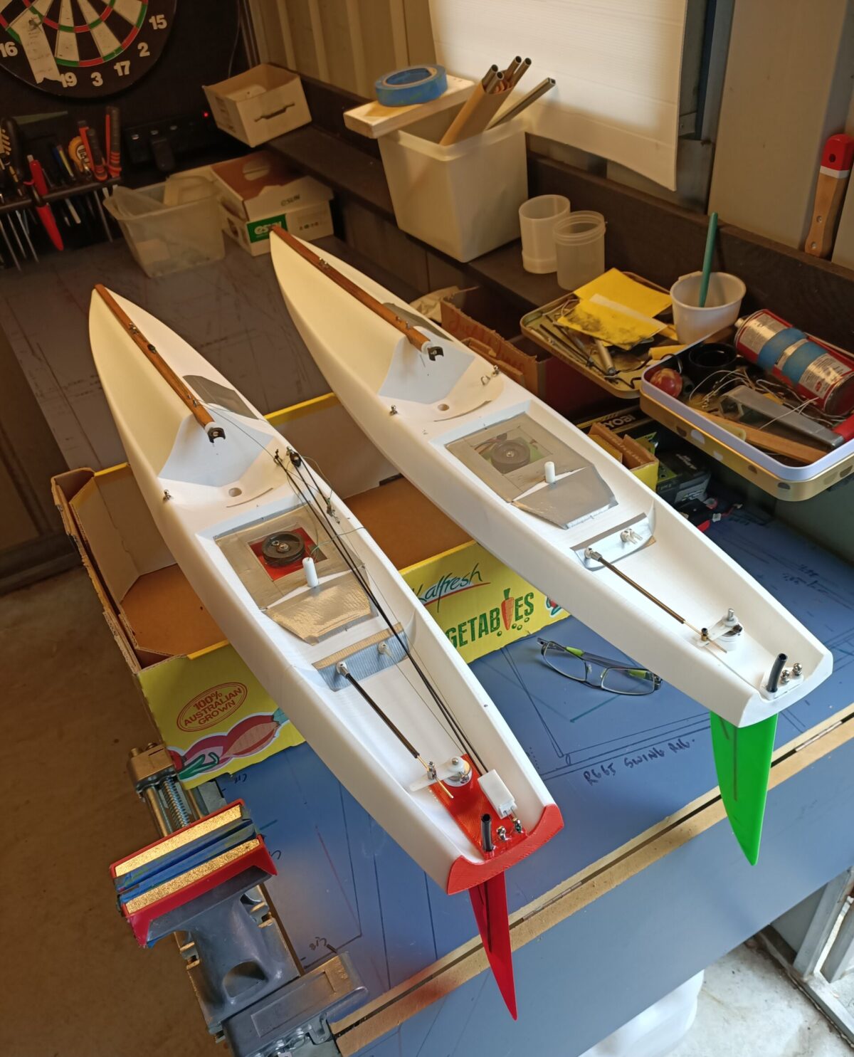
Figure 1. The finished product, our aim today
How do you prepare?
You will need these items to go through the whole process:
- A program called a CAD to draw 3D objects on
- A program to prepare the CAD drawing for printing called a Slicer
- The printer
- A reel of PLA thermoplastic to make the object from
A word on CADs.
If you want to get the most from the potential of 3D printing, I strongly suggest that you source a CAD drawing program and learn how to use it. There are a number of good basic free ones out there such as Freecad (http://www.freecadweb.org/) and Fusion 3D. Alternatively you can Google for free CAD software or if you want more features purchase one or subscribe to one.
It would be a good idea to find a few training videos online to bring you up to speed on CAD drawing. Be patient, you will be investing in knowledge you will appreciate when doing more complex objects in the future.
Another approach is to find someone who owns and can use a CAD. Or, if you have a printer available and want to practice before committing to a CAD, then visit Thingiverse (https://www.thingiverse.com/explore) where you will find literally hundreds of thousands of articles to select from that can be downloaded directly into your Slicer and then printed.
A word on Slicer programs.
A slicer program takes the CAD program and produces the instructions for the printer to lay out hundreds of metres of fine melted fibre from the heated nozzle that slowly builds up to become the object. The object is only as good as the instructions given, assuming you have a reasonably good printer.
There are a number of good Slicer programs out there on the net. Luckily I was introduced to Simplify3d (https://www.simplify3d.com/) at the beginning and for the modest price I have found it amazingly good and very fast. With all the research I have done so far in 3D printing for the sport of RC Yachts, I have yet to go close to Simplify3ds full potential.
So, let’s get started. I am now going to assume you can produce or source a basic drawing similar to this one.

Figure 2. The boom as a CAD drawing
This is a boom section 100 x 10 x 15 mm. It can be sized in the drawing program or resized later in the printer software (depending on your 3D software). The size does not matter that much as long as it can fit your printer.
So let’s get started, these are the key steps.
- Draw the boom section in the CAD to a size that will fit inside your printer volume.
- You may have learnt how to convert drawn objects into shells within the CAD but at this stage it is easier to leave as a solid.
- Save as an STL file where you can find it.
- Go to your Slicer program and import this STL file into the programs workplace.
- Lay the boom flat on the programs workbench ready for printing, wider side down.
- Select two layers for the external shell and two layers for each of the top and bottom layers.
- Select 20% to 40% infill to give internal support without too much weight. This also allows you to print the top layer on to an infill medium and not have a big melted mess that sags down into open space inside.
- Save for printing (it is usually saved automatically as Gcode which is the printer coded instructions)
- Set up your printer with everything on the normal/medium/middle settings and start printing. Don’t forget to use a good adhesive like a smear of glue stick on the base, see your printer instructions. It should take an hour or so, so time for a cuppa.
What have you done here?
You have converted an image in your head into a digital representation in the CAD then used the Slicer to convert this to something the printer can use. It never ceases to amaze me that we now have the ability to think up a useful gizmo, design it and have it in our hands within an hour or so.
But even at this basic stage, there are some traps that can easily be avoided.
First trap. Not supporting the top layer. Without the infill built up inside the top layer the hot PLA will simply sag down into the empty space underneath. We will be discussing in future articles how to think and prepare complex objects for printing to avoid this common mistake. 3D printing does not like overhangs or horizontal layers. They need to be support somehow.
Second trap. The object is too heavy. Infill is an excellent way of strengthening hollow objects like booms without adding unnecessary mass. Experiment with the infill percentage on your printer to get to a balance between strength, rigidity and mass. We are always looking at ways of keeping our beautiful bots on a “diet”.

Figure 3. Note the infill plastic inside the boom. This one only represents 30% of the internal mass (the rest is air) and does a great job strengthening the object but keeping it light
Third trap. Using too many layers. Two to three layers on the external shell usually gives plenty of strength for most RC objects including hulls (more of that in future articles).
Before starting each object, try to put yourself in the shoes of the printer and think about the whole building process as laying out many metres of fine fibre like a long rope or squeezed toothpaste . As you become more experienced, the pitfalls and traps will all be obvious from the start and you will easily recognise them and avoid them.
Why not think about extending what you have learnt here. Some suggestions:
- Experiment with length, shape and cross sections.

Figure 4. If you want more length you may have to print from corner to corner of you printer base
- See if you can design and print a neat tight fitting slider like this one. This is actually rather easy once you have mastered the basics.

Figure 5. Making accessories is a natural progression when you understand 3D printing
Enjoy the journey, lots more fun to come.
Author: Selwyn Holland
Images: Selwyn Holland
END of article 2