A Method For Building A 3d Printed RG65
Author: Allen Roberts (Sydney, Australia)
Images: Allen Roberts, Malcolm Cody, Selwyn Holland
Yacht design: Bill Hagerup
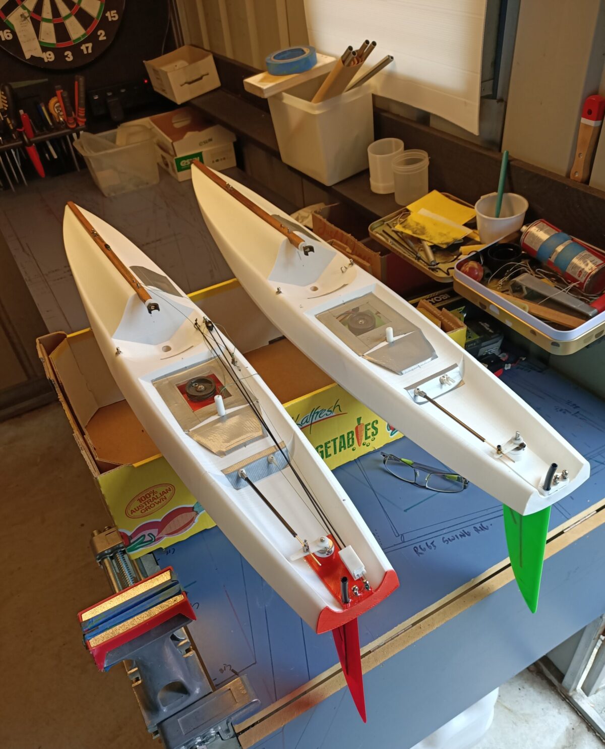
These RG65s are designed to use the running gear from a Dragon Force 65. Makes construction faster and much easier.
Allen recently built a 3d printed radio yacht and I asked him to elaborate on his techniques to achieve that. Allen is a master craftsmen and “go to man” for a lot of Sydney guys when they have specialist things to be done with gadgets and machines. He owns an engineering and manufacturing workshop in Sydney.
Allen kindly put together a summary of his journey through constructing these new style of yachts.
How he did it:
1. To cut a hole for the entry of the ‘finbox/mast socket’:
Place the cockpit frame over the hole just aft of the recess to the blade screw/mast well. Cut inside the frame by 1mm . A useful tool for this job is a Dremmel with a 0.5mm cut off blade or a soldering iron.
2. Glue/ epoxy, the frame to the deck using clamps all around to ensure it is watertight. For practice, melt the inside edges using the soldering iron .
3. The finbox assembly may need sanding slightly to be a snug fit against the inside of the boat. Use a brush to place the glue at the points of contact inside the hull. When solid or dry, use a soldering iron to melt the hull and create an opening for the blade/keel, mast and blade support screw (be careful with the heat, try on a sample first). Blend the edges of the holes together to the finbox creating a water sealed joint.
4. Drill the hole for the rudder using the deck mounted rudder shaft assembly as a guide, then glue it in place.
5. Attach the stern to the hull using the soldering iron , blend the edges , waterproof them!
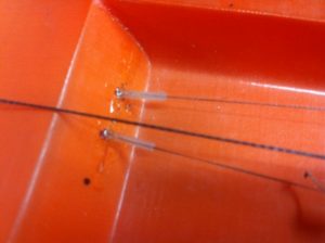
6. Glue 3 pieces of scrap plastic to the underside of the foredeck for support screws to enter from the top. One at the fairlead location, just in front of the mast, One 15mm forward of the jib pivot point and one at the bow .
7. Before attaching the foredeck support rail to the hull, drill a hole 1.2mm horizontally across the rail at the pivot point. this will be the forestay attachment point. Make a loop through the hole and tie off. Now drill a 2mm hole vertically at the fairlead point for the jib sheet to enter from underneath, just behind the foredeck.
8. Attach the foredeck rail to the deck with glue and screws at the 3 places described.
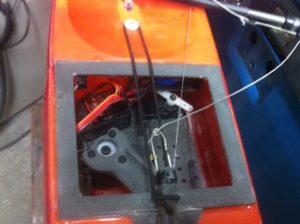
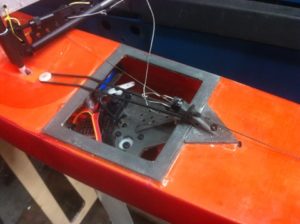
9. Servo Tray: Avoid interaction of the rudder controls and the swinging of the winch arm.
10. The winch servo is not protected from overload, so if obstructed it will ‘burn out’. Keep the winch servo aft in the tray. The swing of the arm must be positioned so the end of the swing is near the front of the boat.This will give a fine adjustment at close hauled.
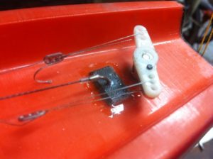
11. Attach the winch cord at a point along the winch arm so that a distance of travel on deck is about 80mm. This distance is adjusted by attaching the cord closer or further from the center of the arm. You need to create a 2:1 ratio, so thread the sheet around the rudder post and attach it back at the servo tray. A small pulley will help for an efficient motion of the sheeting.
12. Cut a space for the rudder servo . You will need to design the best method of control for the rudder, 1 solid rod or 2 cables !
13. The battery can be installed in the foredeck with a ‘tray’ through the deck frame provided. Or on a tray glued to the side of the fin box ,through the cockpit, but be sure to ‘restrain’ it from obstructing the winch arm.
Good luck and I hope this helps.
Allen
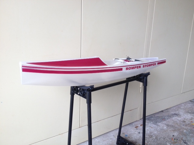
A beautifully finished RG65 from Malcolm Cody built using similar techniques to Allen’s.