Building a Bill Hagerup Banana Design: B1
I will say these are early days, but we have been very much encouraged by this new design direction. Hence we decided to build a series of Banana based yachts across several classes. This is the onging story of the building of B1.
First, what is a Banana Design?
As explained elsewhere, it is a rather unique approach to the downwind performance of yachts. It all started with earlier experiments with the Footy Class and now these discoveries are being “cross-fertilised” to the bigger classes including this IOM. The hull should drive in a straighter line when forced down in a gust and spend less time with the deck under the water. Plus there have been some changes in terms of the efficiency of water flow across the first third of the hull, the crucial connection zone. We already know these changes work on smaller hulls (RG and Footy) now the question is, can it be expanded to the larger hull? We think it can.
The major advantage of using 3d printing technology is the speed at which a new design can be printed and constructed. This one took 24 hours of printing time. In the mean time, the internal parts were designed on the drawing CAD and printed out next.
Hull preparation.
This includes coating the inside with alcohol (metho) diluted epoxy. Don’t forget to prewash the inside with methylated spirits first. Drain excess epoxy, then allow overnight to cure.
Cover the centre line regions with a good quality masking tape. Establish the centre line top and bottom as accurately as possible, I use a laser to help in this area, but that is an optional luxury.
Trace the openings to be cut on the masking tape. Now for a lesson in cutting, I have made more mistakes than anyone so this is worth considering:
- Cutting PLA is better achieved by careful, patient carving with a sharp/fresh blade. A pair of sharp scissors are also ideal for clear flat sections. Yes, I now use a scalpel and scissors… why is that?
- Cutting PLA with a Dremel type device requires a spinning thin blade. The blade needs to be spinning at a low speed but not too low. This is the problem, the blade cuts and also instantly melts the edges of the cut causing a messy edge. Also, it is very hard to go around corners with the spinning blade.
- A flat spade screwdriver head attached to a soldering iron head will help melt your way around a corner, but again it leaves a melted rough edge that is hard to clean up.
- There are other ways to get the job done, but I would strongly suggest that you be patient with a sharp blade and keep cutting along the traced pencil mark until it neatly cuts away. It really does make a nice edge and is reasonably fast with practice.
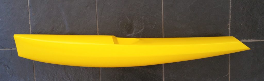
Finally, after trialing many different surface preparations we have found it is easier and far more effective to leave the hull surface raw as it comes from the printer. The hull is tough, resilient, and UV resistant to fading. The colours are in the printed PLA and therefore nothing needs to be done to the surface.
Construction is fairly straight forward.
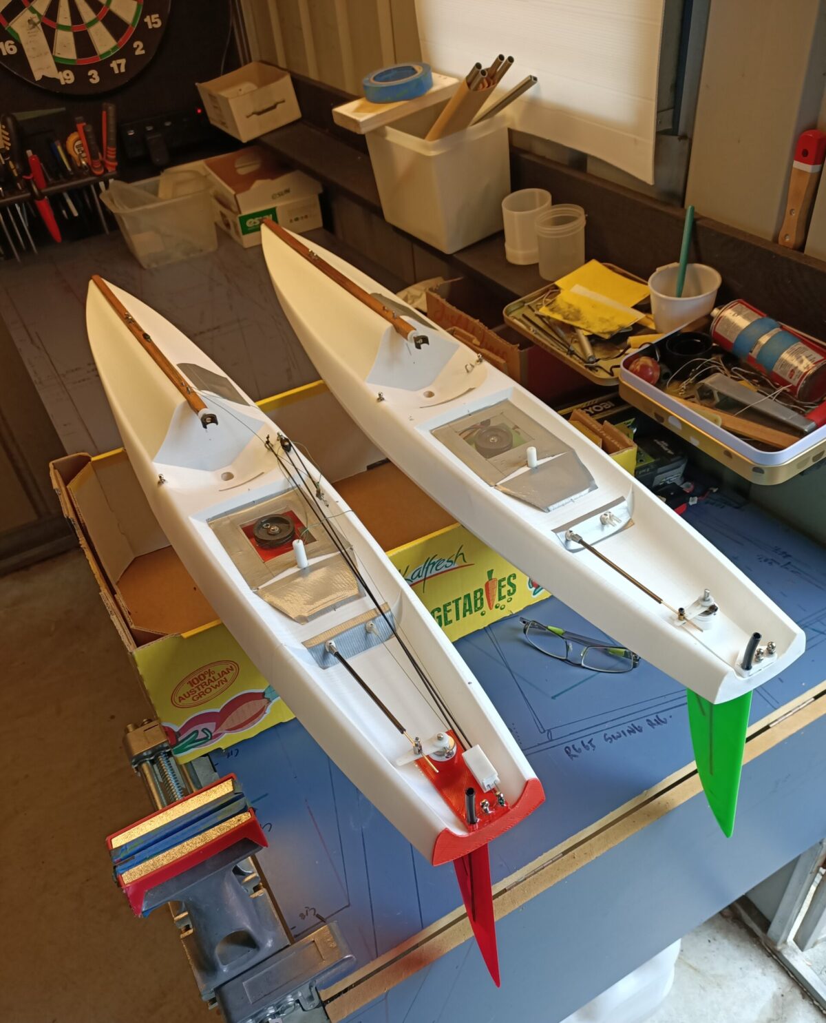
The rest is making sure everything lines up and you prepare the surfaces with some fine sandpaper before epoxy gluing. In my designs everything that possibly can be is made by 3d printing. A big advantage is how fast a new design can be created for a part if it doesn’t fit exactly or needs reshaping. This image shows the hull partly prepared and all the parts to be installed.
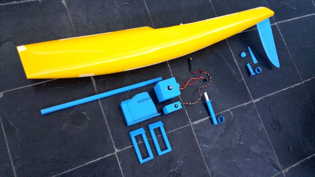
Here are some key items.
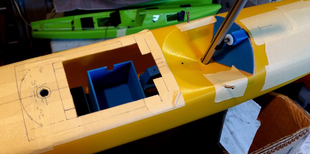
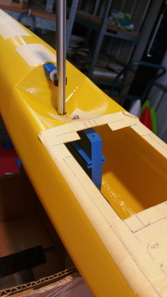
Keel Case and Support Struts
It may take you some time to get a keel case designed and nicely fitting. But it is worth the effort. It can be reprinted over and over again for new models.
The struts are there to add extra compressional strength between the hull and the base of the keel case. Whatever you design will be fine as long as they are strong and lightweight.
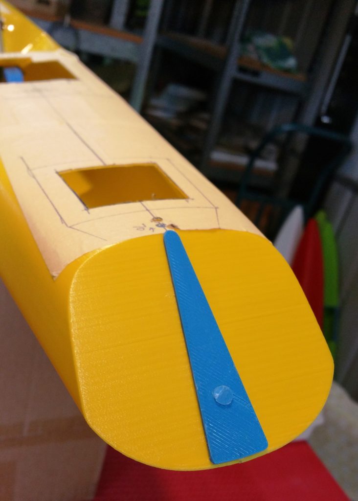
Rudder and Supports
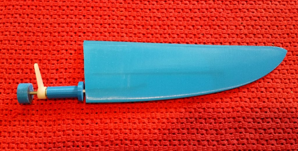
Don’t be afraid to make a rudder for IOMs. I keep them simple with a support strut down the middle for rigidity and turn the 4mm shaft at the end to stop twisting as time goes on. These can be seen faintly through the surface material. Notice the rudder shaft projects up into the support cylinder which will be set under the deck.
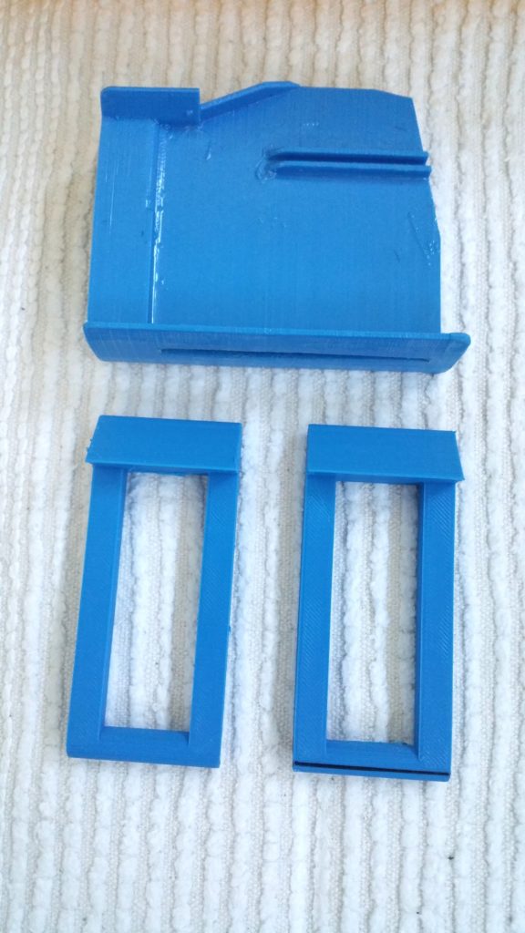
Waterproof Housings
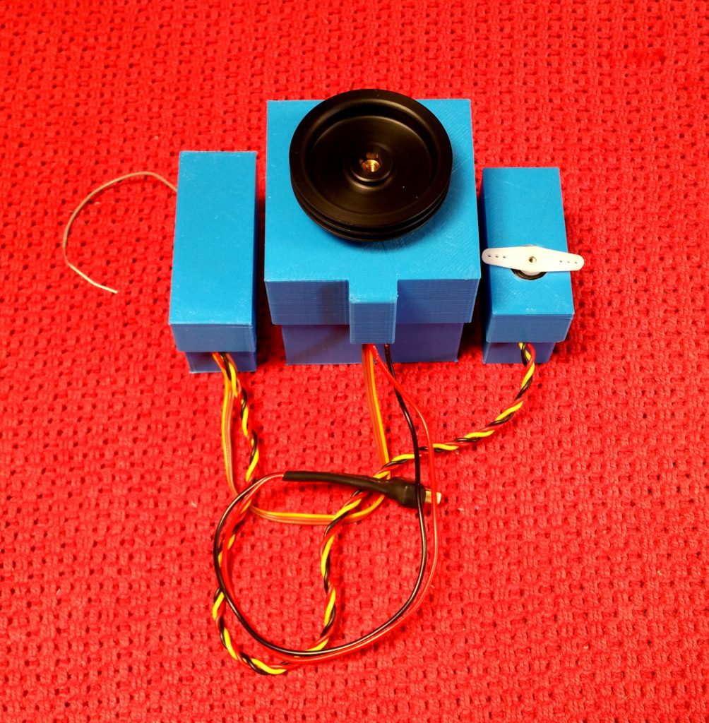
Lets face it even the best boats leak sometimes, others needed draining after every race. I got thinking, after a design session with Craig Smith where we designed in a waterproof winch system to be printed with the hull, so I thought about the idea of water sealing the winch, servo and receiver in their own containers. These lightweight containers can be used on any boat, the bases are simply glued to the base of the hull and the gadgets are secured to the inside of the lids. Spares can be pre-attached to their own spare lids ready to change in a jiffy if necessary. Make sure the lid sides are longish and firm, they should stay in place without securing, just think about the direction of the force vectors.. they are all at right angles to the lid.
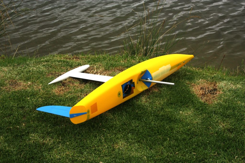
Following are images of the rest of the construction phase up to the float test. More as the project continues…
![]()
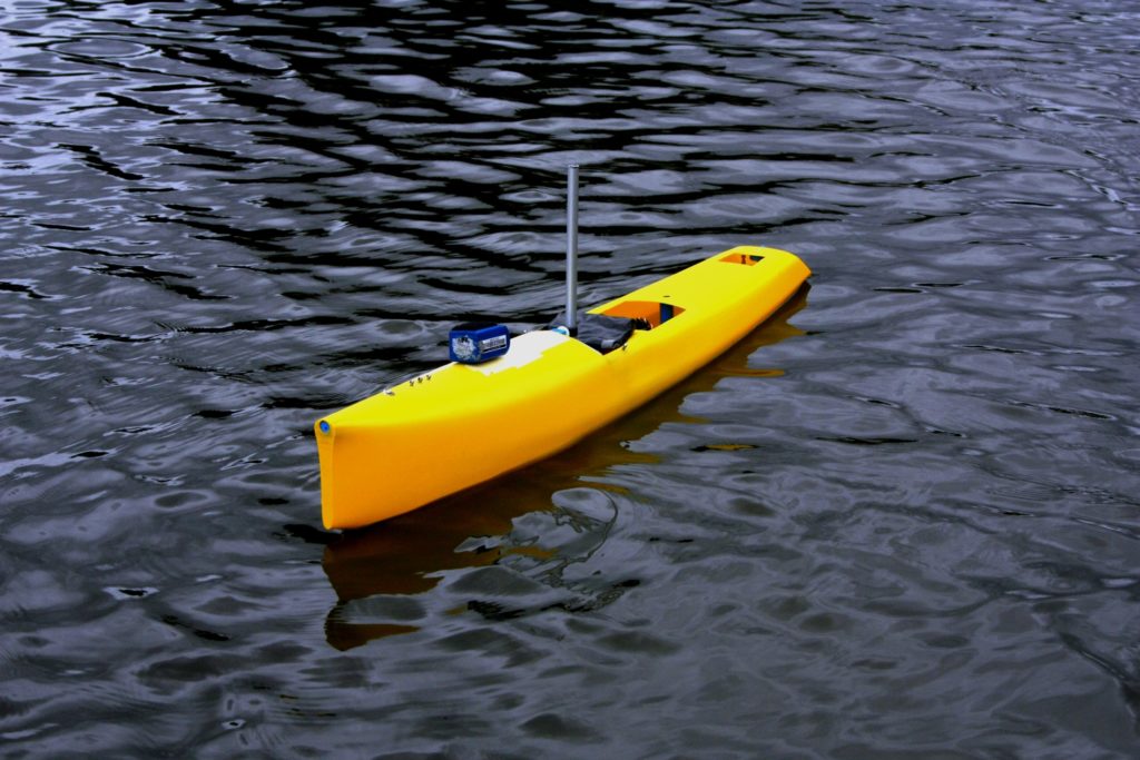
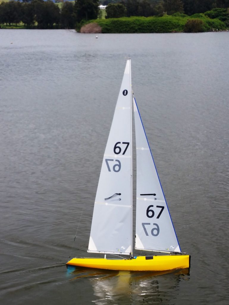
In water now.
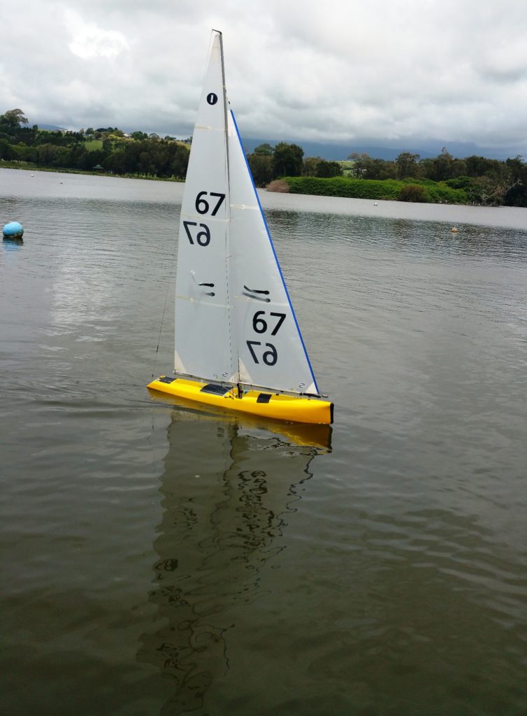
Beautifully balanced and racing in the club it is showing very good speed and agility. Like all new boats they take a little time to settle in, but initial impressions are excellent.
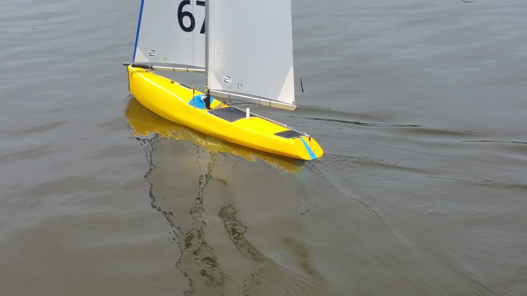
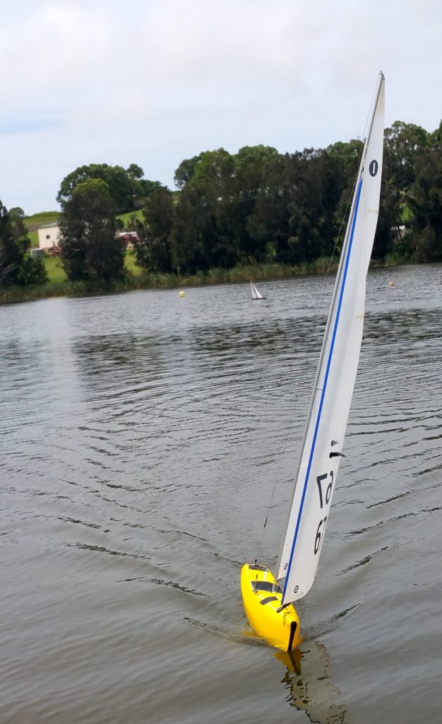
I’ve had some club racing now with B1. This is definitely a keeper.
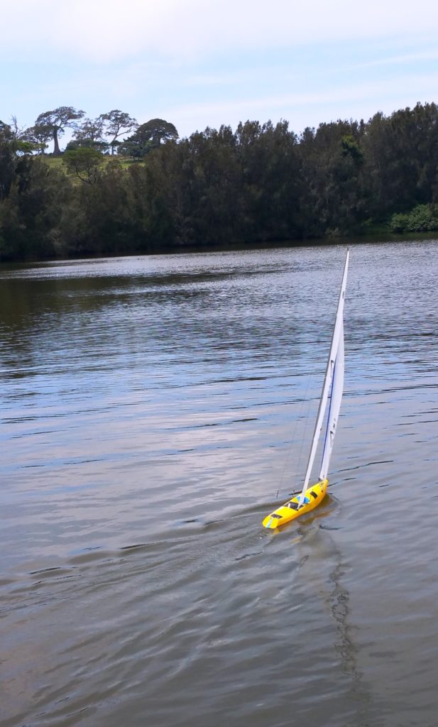
Have had a chance to watch it duck dive in downwind gusts and just what Bill showed with the Footy happened.
It would duck and pop back up in a straight line, while most others are screwing around. The only time it got flattened was when everyone else got flattened as well. I think we are on to something here for down wind performance in gusty conditions. Also seems very competitive in the lighter conditions.
Watch this space for more.