This is Like an Elephant in the Kitchen
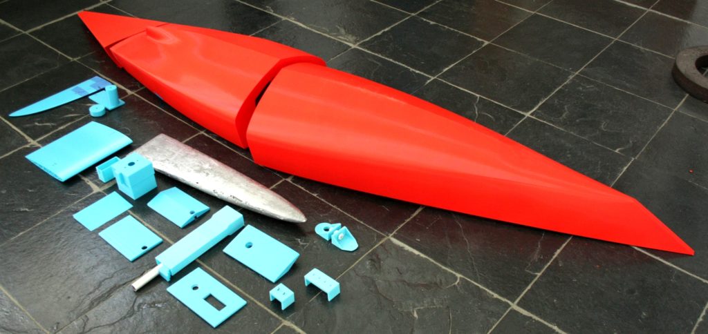
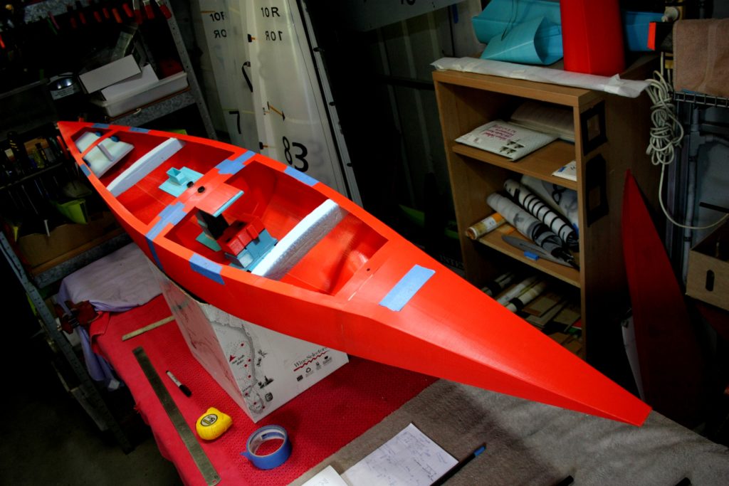
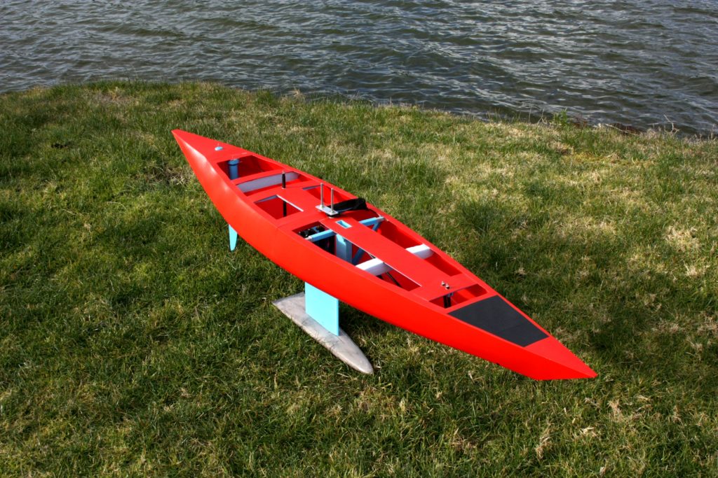
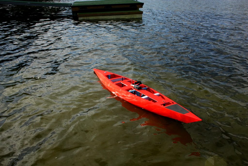
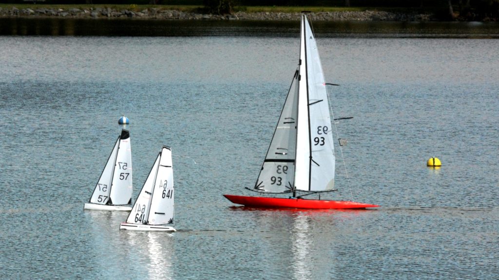
First, I would like to thank Graham Bantock for his brilliant new yacht. The Spear is a new digital design and fits into his family of A Class yachts between the Gunboat (lightest) and the iconic Sword in the mid range. We started chatting some 6 months ago about the design and how to get it into a form that could be printed easily. As you can see it has all happened, the first prototype has arrived.
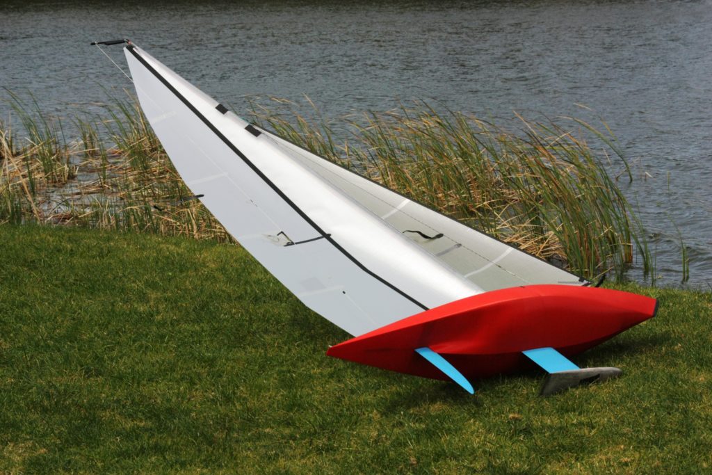
At 2m (yes, 2000mm) long and displacement of around 14.5 kg this is a real beast and the construction challenge involved an interesting blend of the latest 3d printing material and innovative engineering.
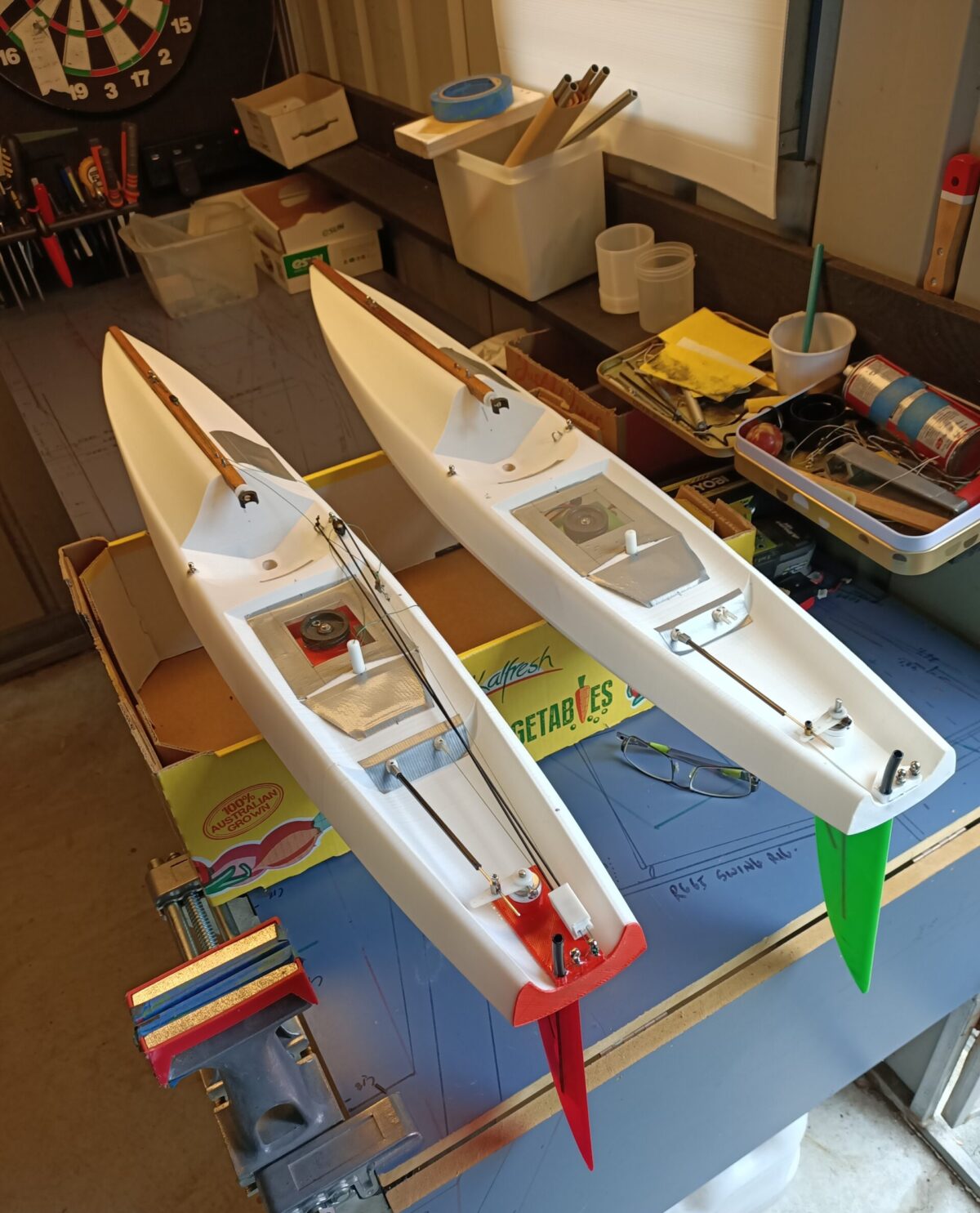
This really needed some lateral thinking to get a finished product. The process of producing an RG65 and IOM is a piece of cake compared. With these two, the PLA+ from eSun is almost stiff enough to hold good tension in the rig by itself. But to help, a forward horizontal strut attached to a vertical strut through the deck to the base of the hull was all that is needed to produce a nice tight rigged yacht.
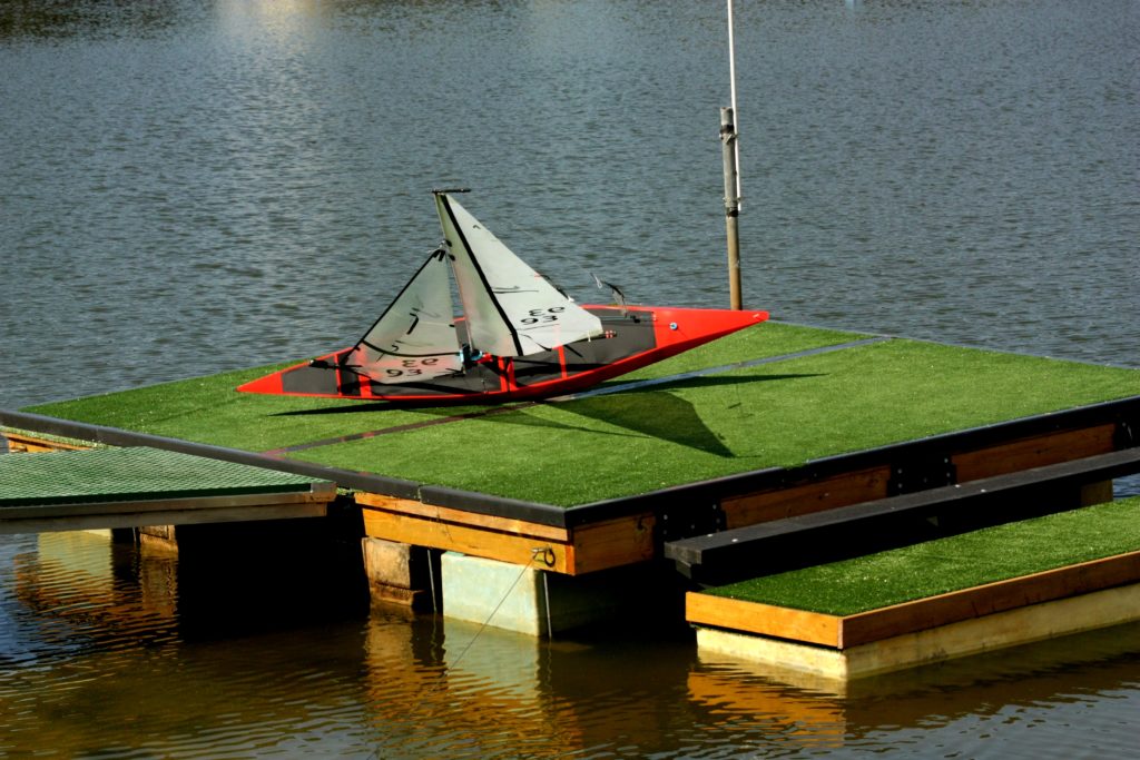
But with a 1998mm long A Class and a much… much bigger sail area, the stresses and forces start getting scary when one is trying to keep the hull as light as possible. Plus keep the ballast to hull mass ratio competitive.
So rather than use a lot of words, this story is mainly written in images. Feel free to contact me if you want more detail, as you would suspect by now I am working solidly towards promoting this technology as an alternative to carbon and fibreglass in our beautiful sport: (selwyn.holland2@gmail.com).
The key points of the design include:
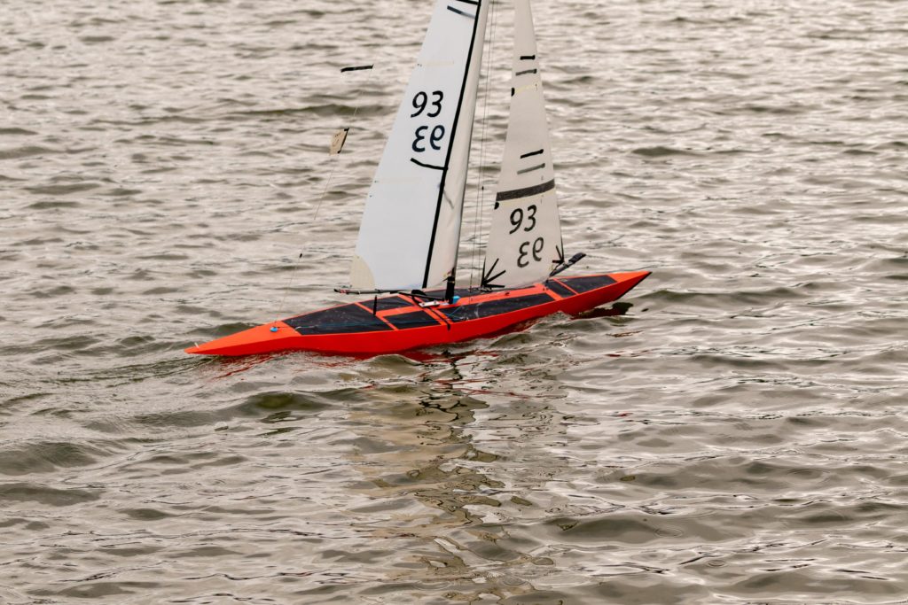
- The hull skin thickness was kept at around 1.1mm
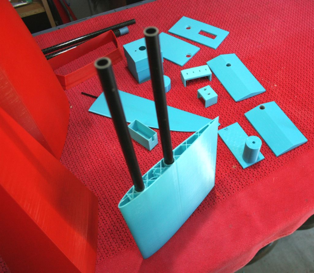
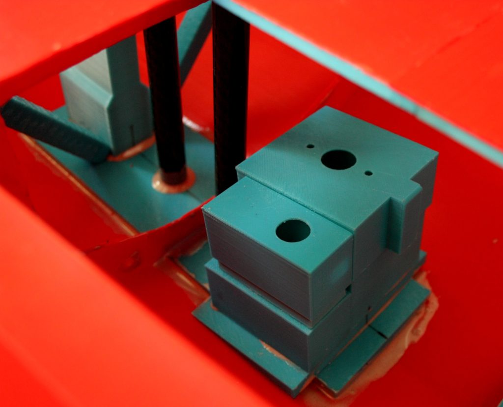
- The “solid” sections used a combination of fill patterns and were printed as light as possible. It is amazing how stiff a “solid” piece can be with say a honeycomb inner pattern and only 15% infilled.
- The thermoplastic feedstock was PLA+ from eSun
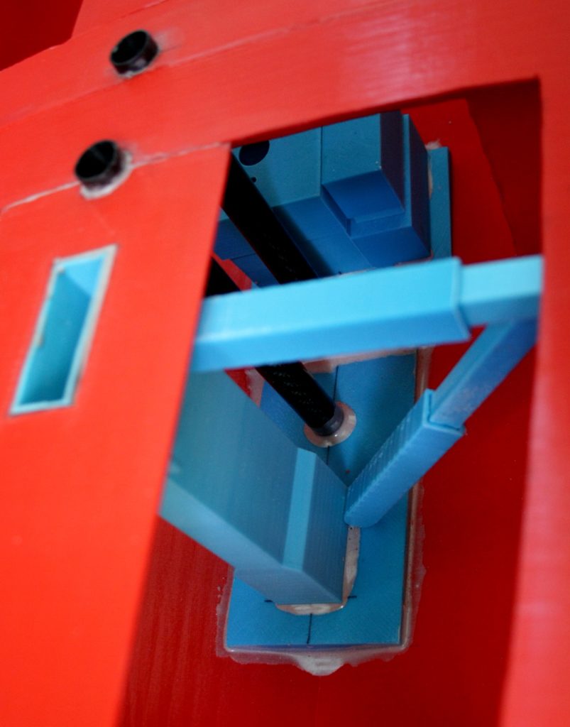
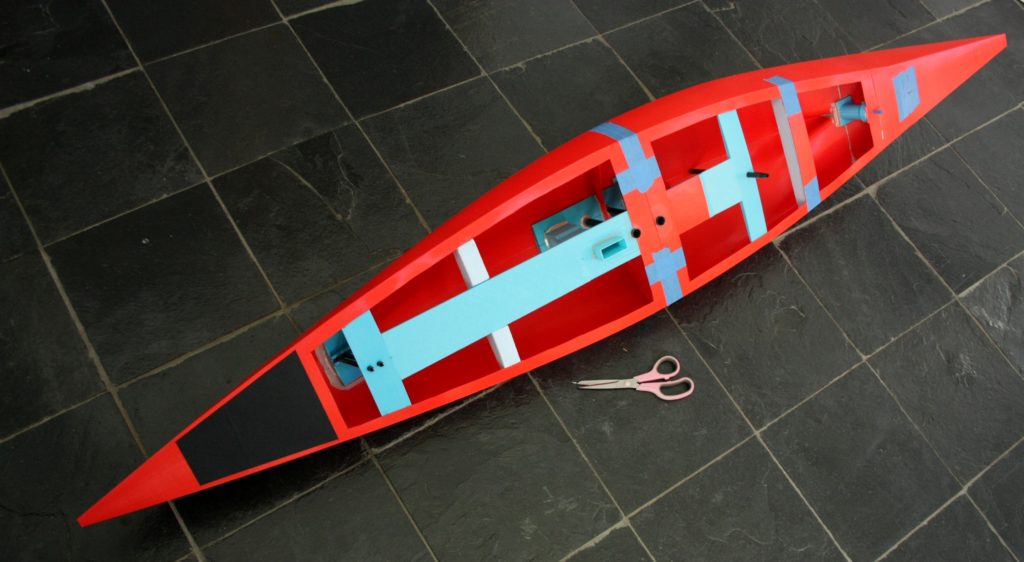
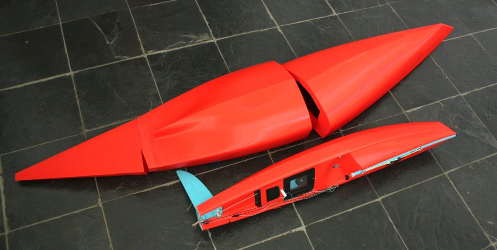
- The central (half way) join was a bulkhead with a cut section to allow the two halves to be open to each other. This is a key stiffening factor in the main support region for the keel and ballast. Other sections can be sleeved.
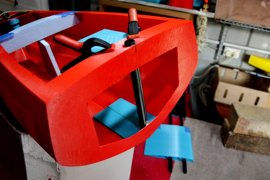
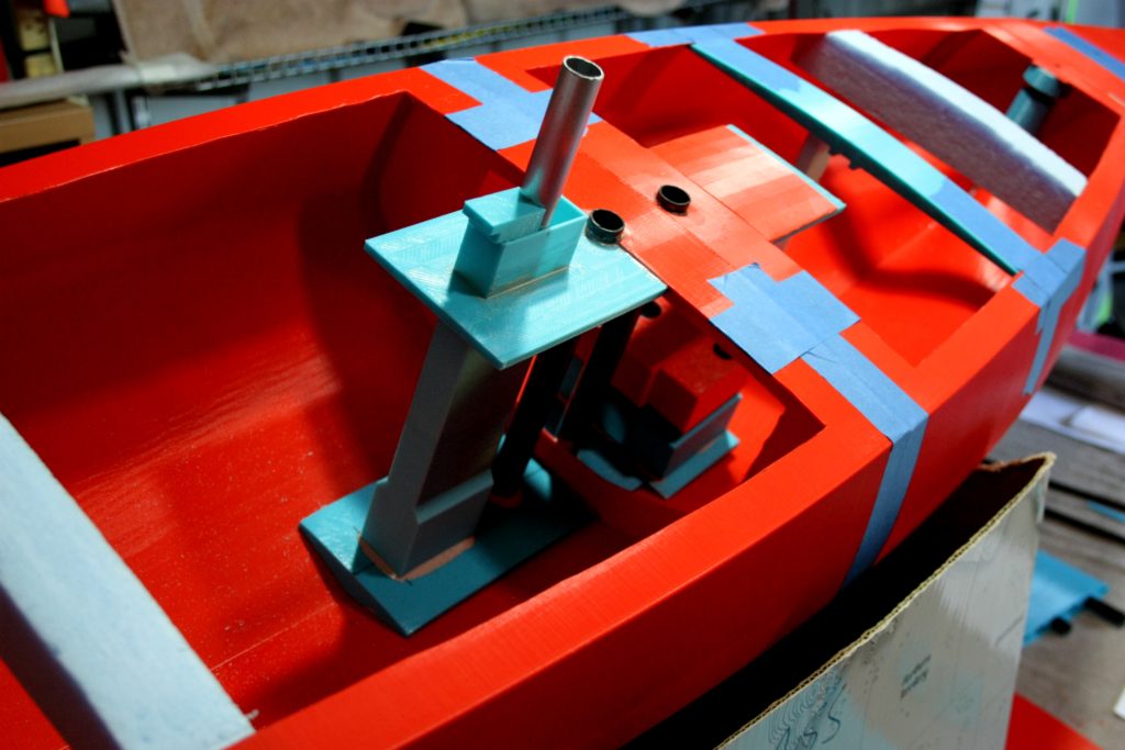
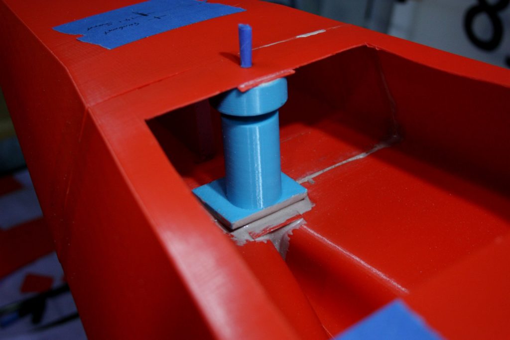
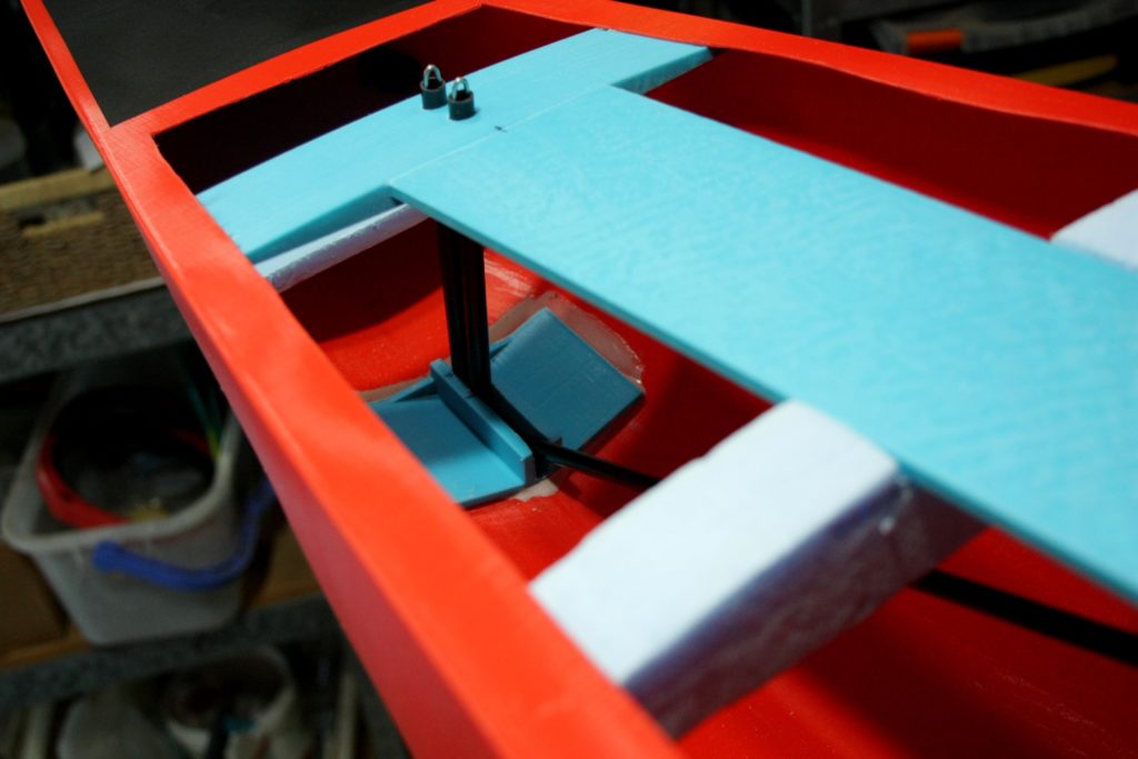
- The original deck was cut back to allow for a H shaped “spine” to be inserted between the sheet post and the forward jib boom swivel. This is hidden under the deck and along with the central bulkhead helped create a very stiff upper hull to compliment the natural strength of a rounded lower hull section.
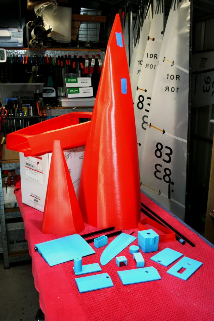
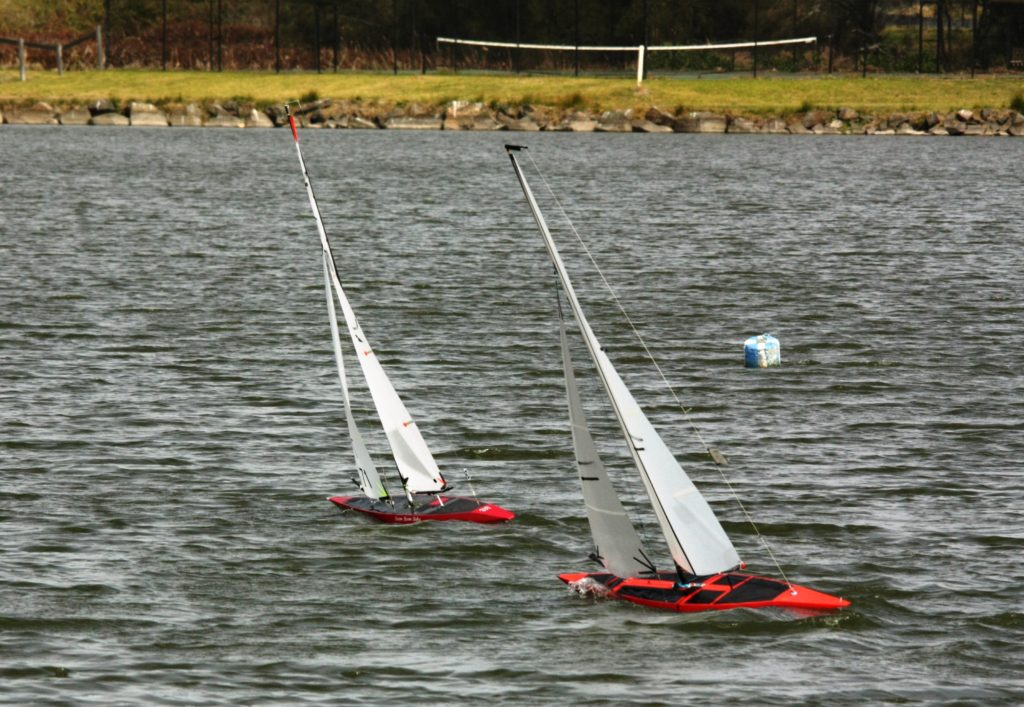
- To improve the jib stay stiffness a carbon tube was inserted between the base of the jib swivel tubes up to the top of the mast slot. So when tension was applied to the forestay, the triangular structure would resist flexure in the system.
- The keel and ballast are hung off a pair of carbon tubes and 6mm stainless steel threaded rods leading up through larger carbon tubes to the deck. Screwing down the nuts on the deck pulls the ballast and keel up against the bse of the hull. Also nice and stiff, plus lightweight compared to a keel box and keel projecting into the hull.
- In essence most of the stress and forces (and therefore stiffness) are handled by the three dimensions of the bulkhead (X and Y axis), the spine (X and Z axis) and finally the forestay triangle (Y and Z axis). The hull basically only supplies the bouyancy to float the system.
- The images will help you understand.