Print Your Own Yacht: STL File Downloads
Welcome to the download site for files developed throughout this project and others.
These are many of the files that have been designed, printed and trialed in various radio controlled classes for 3d printing in small and large printers.
If you have any good designs you are happy to “float” to others here, please feel free to send the STL files to me at: selwyn.holland2@gmail.com
Make sure your name is on the files so that you can be credited with their design.
All files supplied here are copyright free.
Note: these are all zip files and need to be downloaded as such.
And…probably a good idea to read through the notes here before you launch into the printing.
The basic items needed to produce a racing yacht are supplied, but things of a specialist nature will be up to you. In some cases there are multiple parts to choose from. For instance there is the Keel Box I use on my RG and there is also one designed for Dragon Force keels and bulbs… because there are a lot of them around and good for beginners to easily get into the sport. In fact the rig I have always used on my lovely RG (yes the design you have here) is taken straight over from a DF but using my own sails. There are multiple rudder tubes and open and waterproof servo supports to suite a variety of yachts also.
Plus the advantage of digital technology is that parts can be resized in the Printer software to fit other yachts. If you haven’t already done so, I strongly suggest you invest in what is considered the best and fastest 3d printer software package: Simplify 3D at www.simplify3d.com/
So if something doesn’t quite fit, just adjust on the 3d software. You don’t have to redesign from the beginning. Make it bigger, fatter, thinner….
All of the items listed here have been designed to be printed without 3d supports. Just change the orientation to find flat spot to place on the table. Hulls can usually be started from the bow or the stern, the deck angles are all determined to allow for solid 3d printing and no need for bridging.
If you see things on the images that are not in the files, it is because I most likely don’t use them any more. The latest versions have been thinned right down to keep the weight as light as possible. For instance I have stopped using pot surrounds because the new PLA+ (mentioned elsewhere) is very rigid and strong. Do yourself a favour and get hold of some to try out.
Please be patient with all this, things will evolve as time goes on.
Contents:
A. Files from Bill Hagerup and Selwyn Holland
General Rudder design
Bulbs for you to resize to your yacht
Waterproof boxes for winches and servos
Nano plus bits and pieces
RG65/65 Class plus bits and pieces
Footy plus bits and pieces
IOM Sabre a lovely fast design
B. Detailed description of the pin, sheeting and deck layout
C. Files from other 3d printing radio control enthusiasts.
Happy to host your special files here.
A. Files from Bill Hagerup and Selwyn Holland
General Rudder Design
This design was very early on in our research and turned out to be a great all round rudder. It has been used on everything from the Footies to the prototype 10R. Big advantage is simplicity of construction and you can vary the size to help fine tune the boat.
All I do is use a stainless core rod and a single solid carbon rod to add a bit more rigidity. All rudder printing is in “Vase” or “Spiral” mode (the same), this gives you a light hollow shell to work with.
General Rudder size to fit any sized yacht (Hagerup Holland)
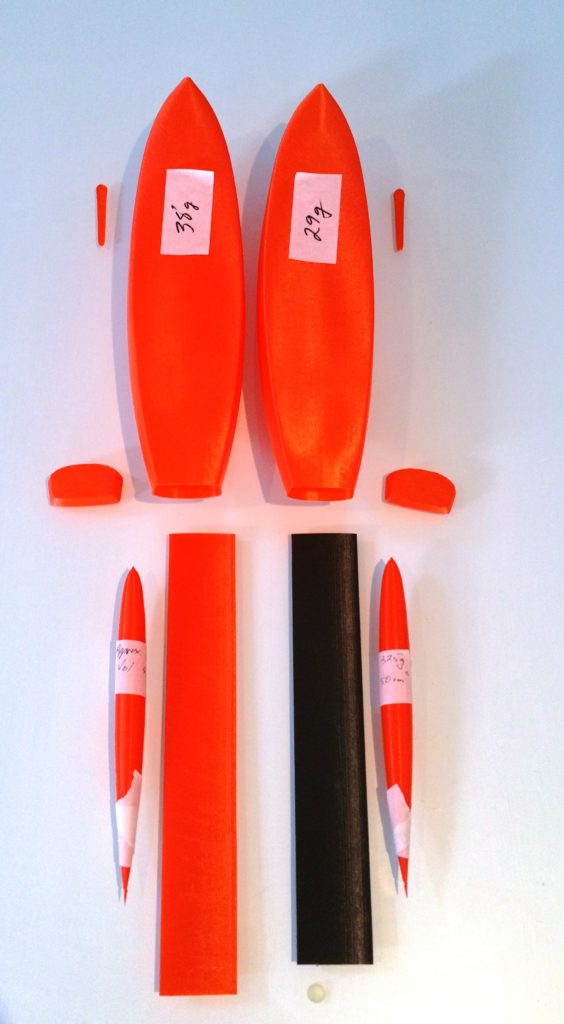
Bulbs for you to resize to your yacht
Both shapes appear to be efficient at the speeds we use in the smaller RC yachts. Fill them with the finest lead pellet you can source. Add a small amount of epoxy then some lead, let it settle, then repeat until full. Be patient, it takes time. I could not pick any difference in performance between these and a traditional lead bulb. Yes, there is more volume but you get an excellent shape and can determine the mass you wish before printing. Make sure there are no air bubbles left in the bulb, this gives unwanted bouyancy.
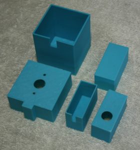
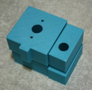
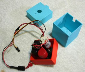
Waterproof boxes for winches and servos
About 18 months ago, I designed a set of waterproof boxes for the winch, servo and receiver in my yachts. These went through various stages of development as you would imagine. It is now very hard for any fresh or saltwater to get to the electronics, as a result my yachts have been completely free of electronic issues and corrosion. I still coated the exposed metal items with vaseline or similar long term oils before sealing and this acts as a second line of defence. I see all around me people having corrosion issues, but this appears to have solved the problem for me.
As an example supporting this move, I unfortunately had an incident that filled one of the IOMs half full of water due a few months back, lucky to get it back to the wharf. I drained the water out, went home and pulled the waterproof containers apart and there wasn’t a single drop of water in any of the boxes. A great result.
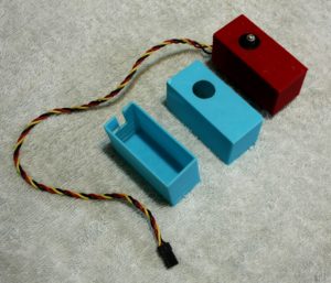
There are two sets
1. IOM and bigger yacht boxes.
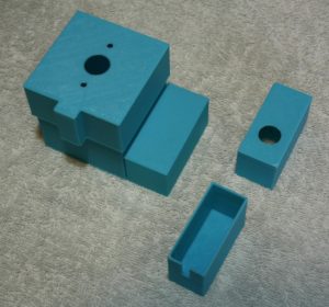
They are all the same for convenience and set up for Guyat Winches and Hi Tech servos. Part of the easy “lego style” approach to the RC yachts. They can be kept together in what I call ‘The Stack” or glued in seperately, however you wish. Use them for your other designs, why get you electonic bits wet if you don’ need to.
Please note. Depending on your 3d flow set up and nozzle size, you may have to play around with some resizing to get the boxes to fit each other smoothly.
Box Winch base v7 63×63 2mm wall (Holland)
Box Winch base v7 63×62 1.5mm wall (Holland)
Box Winch lid v6 1.5mm thick wall (Holland)
Box receiver base v1 (Holland)
Box receiver base v2 (Holland)
2.Smaller Yachts: RG65, 65 Class, Nano, Footy
These yacht sizes tend to use the same servo type for both winch and rudder. So the set are the same… just make two of them and offset the vertical stack a bit to allow for the rudder horn to swing underneath the sheeting arm.
Nano Bits and Pieces
Nano Hull NanoSwing 2 (Hagerup Holland)
Nano Keel Box V8 Nano 40x4mm slot with supports and finished (Holland)
Nano Keel standard 300mm size to fit (Holland)
Nano Rudder (shrink to size) (Hagerup Holland)
Nano winch servo shelf blank Holland
Nano rudder support 8mm diam round 3.3mm inside hole Holland
Nano rudder servo shelf blank Holland
Nano rudder deck washer 15x2mm 8.7mm hole Holland
Nano back stay fastener (Holland)
RG65/65 Class Bits and Pieces
Dragon Force Keel version. The keel box was designed use a DF keel so anyone wanting to get into an RG65 quickly and easily could transfer their DF gear over and start sailing.
The Deluxe “Go Fast” set up with 3d printed keel, bulb and rudder. This is a more traditional RG65/65 Class design with a keel to fit. Use carbon rods down the middle to give it stiffness. Fill the bulb with fine lead shot and epoxy mix (bit at a time). A bit more volume but the shape is very efficient and I can’t tell any performance difference between this and a lead bulb. Size the bulb on your 3d software to get the exact mass you want.
RG65 Hull Alpha Sabre (Hagerup Holland)
RG65 Keel Box V10 48x5mm slot with supports and finished (Holland)
RG65 Keel Box for Dragon Force keel V6 Holland
RG65 General Rudder file size to fit (Holland)
RG65 Shelf V9 open blank stepped Holland
RG65 Rudder support internal 3mm hole x 10mm diam Holland
RG65 Rudder internal support 3mm hole Holland
RG65 Glue pot v2 20x10mm Holland
RG65 Box Servo lid v2 waterproof change to fit base Holland
RG65 Box Servo base waterproofchange to fit lid Holland
RG65 Foreword support strut v2 tappered 4mm hole (Holland)
RG65 Back stay fastener (Holland)
Footy Bits and Pieces
The Footy is one of Bill’s favourite yachts.
These two hulls represent the final stages in our research for an optimum hull shape and lightness for these little fellas. The main differences is around the bow, the “submarine” was designed for quick recovery and less “tripping” when knocked down while running … they seem to spend a lot of time under water going down wind because of their huge sail area to water line length.
The other hull is a more traditional shape with a sharp tumblehome. Try the difference and let us know what you discover.
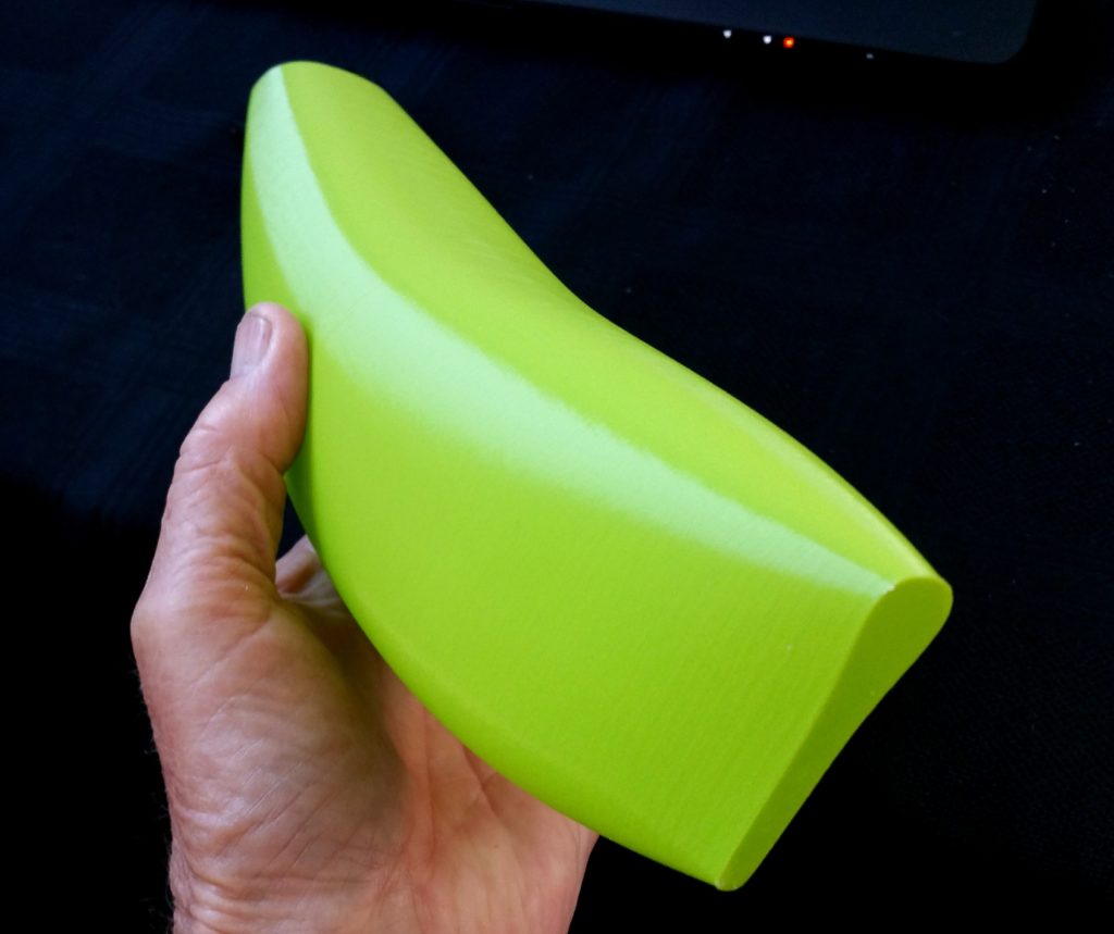
The above hull is an example of what can be done with a smallish printer. Bill Short produced the two parts of the hull seperately using the printer software and then sleeved them together. Very nicely done for his first attempt. The other “bits” also came out nicely. The Footy is a great sailing yacht and an easy one to start with.
Hull FootPrint6. submarine bow (Hagerup)
IOM Sabre a lovely fast design
This is the latest IOM prototype from a longish development period going back over two years. As stated elsewhere, we were very reluctant to release a design until the right material had been found (PLA+ from esun) and the boat was competitive.
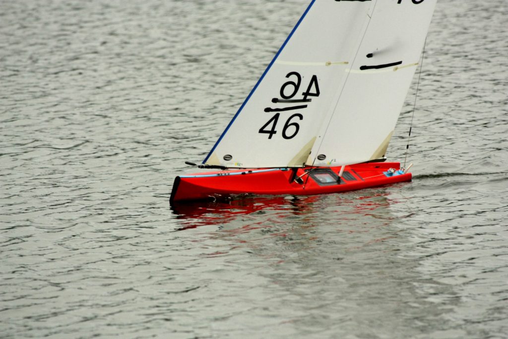
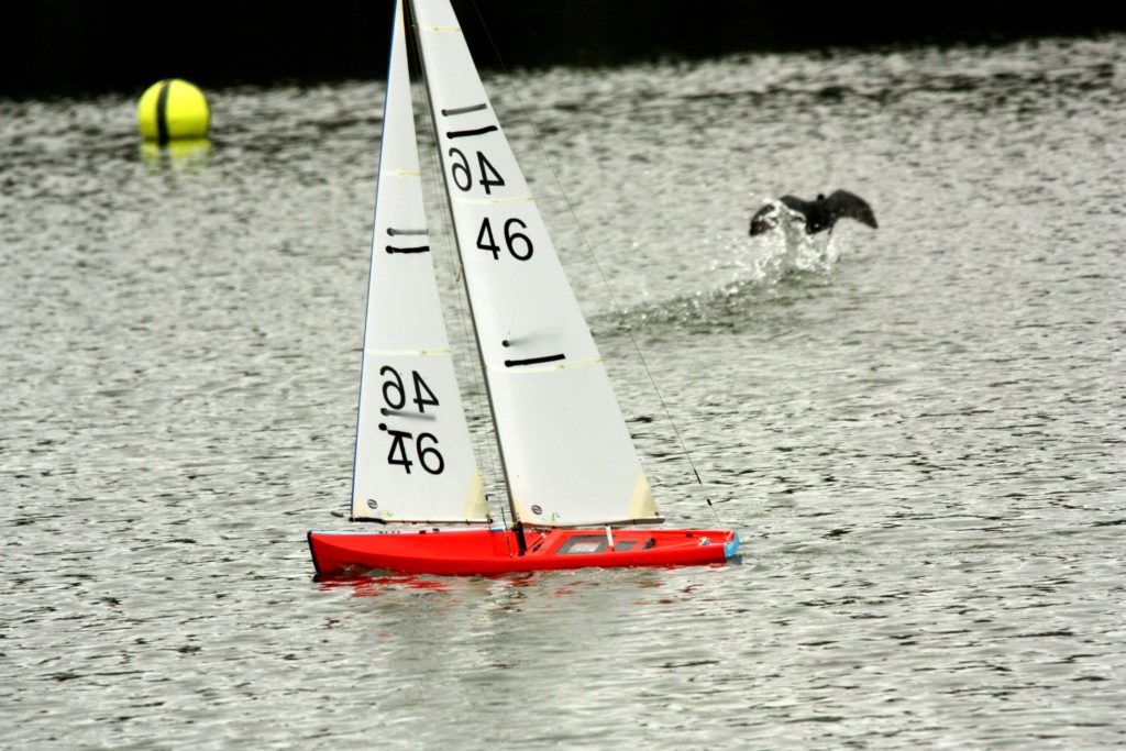
So, introducing the Beta Sabre from Bill Hagerup. I’ve been sailing this design since mid 2018 and love it. It seems fine across the spectrum of conditions from short chop, long wavelength and flat ponds.
Beta Sabre 3D (N0. 46)
I hope you enjoy it as much as I am.
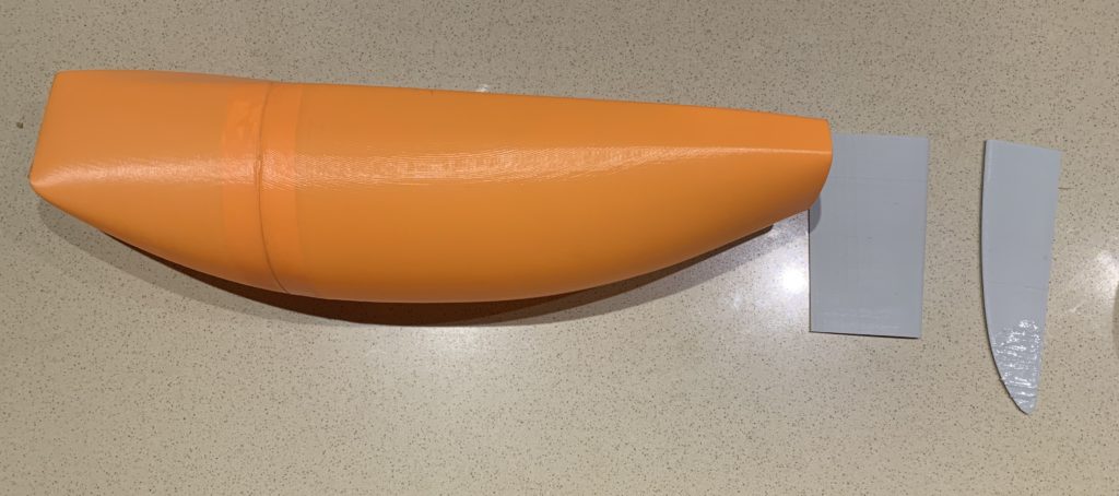
In combinations with the waterproof boxes shown earlier, almost all the bits and pieces you need are here as STL files. You will need to make your own 10 mm thick bumper and create a stern or bow plate by printing 4 or 5 layers of a hull and stopping to give you the shape to glue in place.
Don’t forget the “lego” nature of all this, please feel free to use the fittings for your other yachts as you wish. They are all copyright free and we are gifting them to the RC community to help promote our beautiful sport . We will all win from you guys going out there and making this all happen.
I have often read: “When All Else Fails…. Read The Manual”
Well we don’t have a manual here, so how about: “When All Else Fails… View The Construction Pictures”.
Rather than try to explain everything, have a good look at the set of images below showing the various key construction processes. If you are unsure, please feel free to ask at: selwyn.holland2@gmail.com
The STL files are at the end… yes you may need to do some minor resizing as needed. This is easy through a program like “Simplify 3d”.
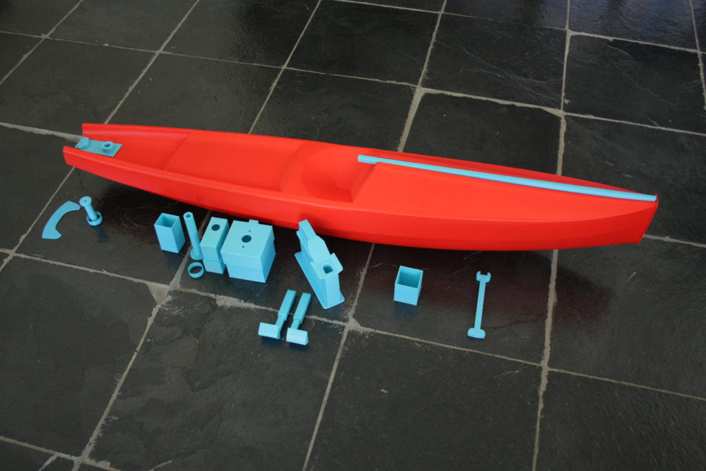
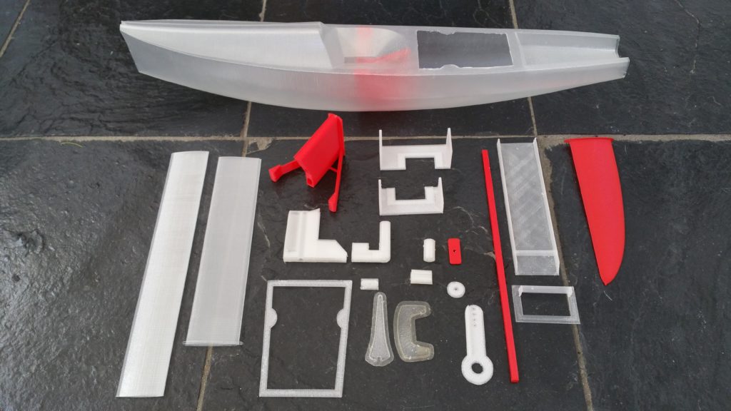
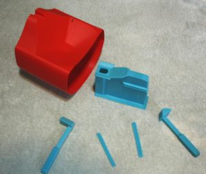
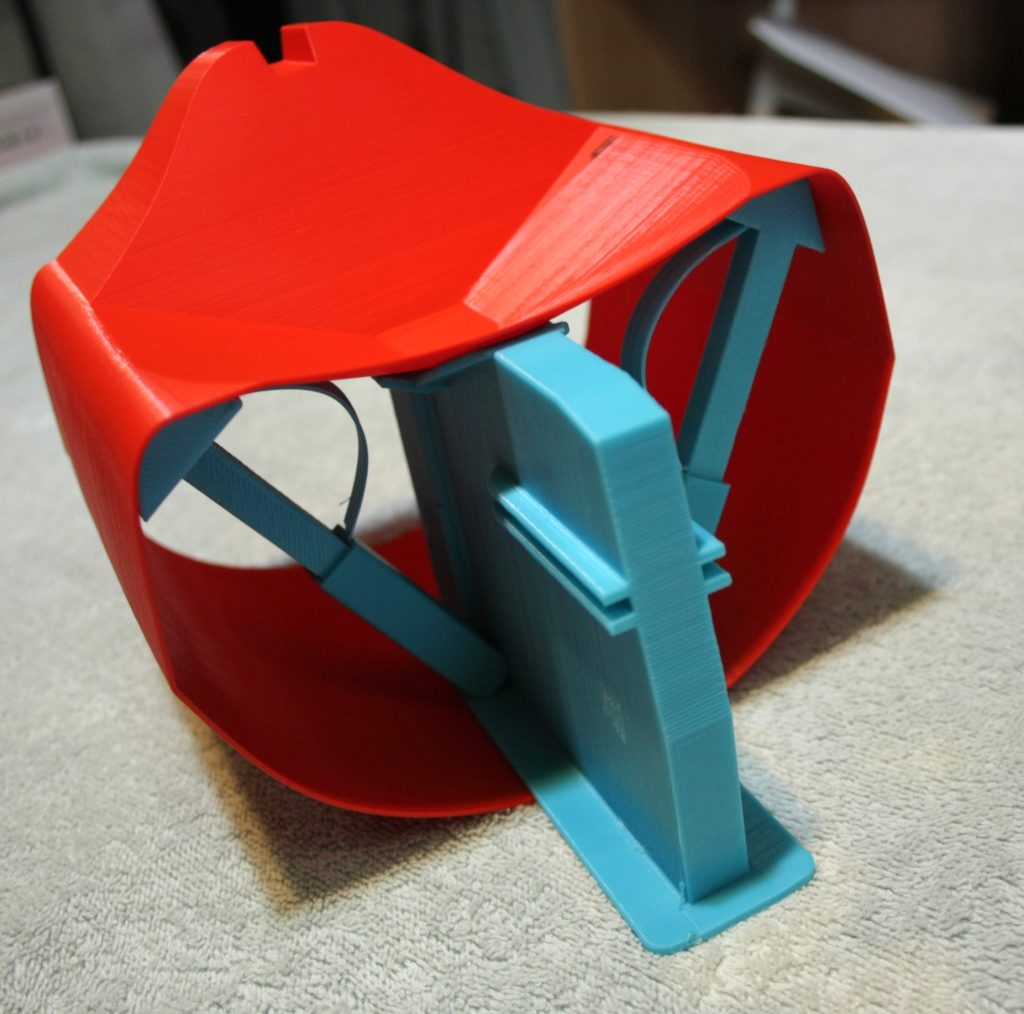
This is what you get to make the following:
A couple of things to be aware of:
- The keel is designed around the latest Craig Smith fin design. If you can’t get this keel and have another, no problem, just work out you dimensions in cross section and change the slot profile until it fits. Then trim you keel head to fit inside the box. The last item is to fit the holding bolt in the right spot.
- The keel box support struts are telescopic to make them easy to install. Follow the pictures to see how it is done. To hold them in place I bend a small strip of PLA and add to the sliding section to give some tension to hold the head in place before the gluing.
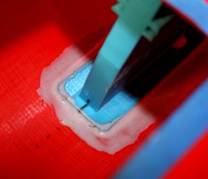
- When using epoxy, add some filler until it is slow to flow. This helps strengthen the adhesion. Straight epoxy is not as good by itself. Also prepare the surface by rubbing with methylated spirits (ethanol) to remove the slight greasy surface that comes with 3d printing then sand both surfaces with a relatively coarse sandpaper. Try to keep the epoxy volume to a minimum. The PLA+ and epoxy adhere strongly.
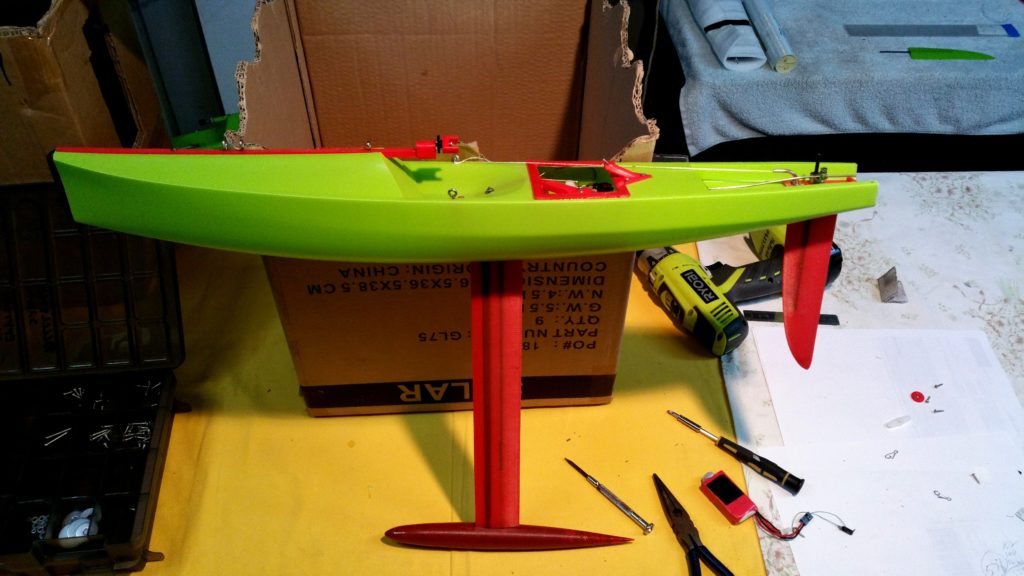
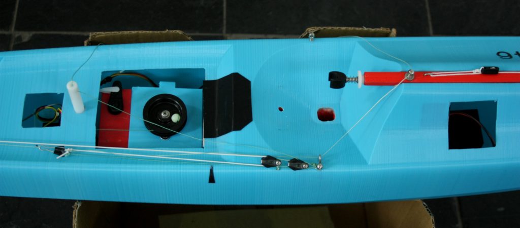
- The boat appears to be nicely balanced with the battery pack ahead of the mast as shown. But it is up to you how you wish to set all this up.
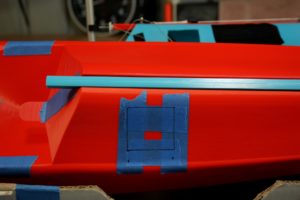
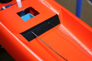
- The rudder rod and sheet are run through the false transom at the stern. Once the position of the hole is worked out and made, I use vinyl tape (not insulation tape) to add extra support for the movement. I did this originally as a short term solution and have been using it ever sense. Easy and waterproof.
- When cutting and creating holes in the this PLA+ run the Dremel or drill at the lowest possible speed to stop the plastic from melting. This material cuts very nicely. I use heavy duty scissors for flat sections.
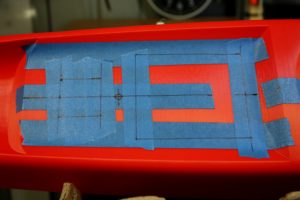
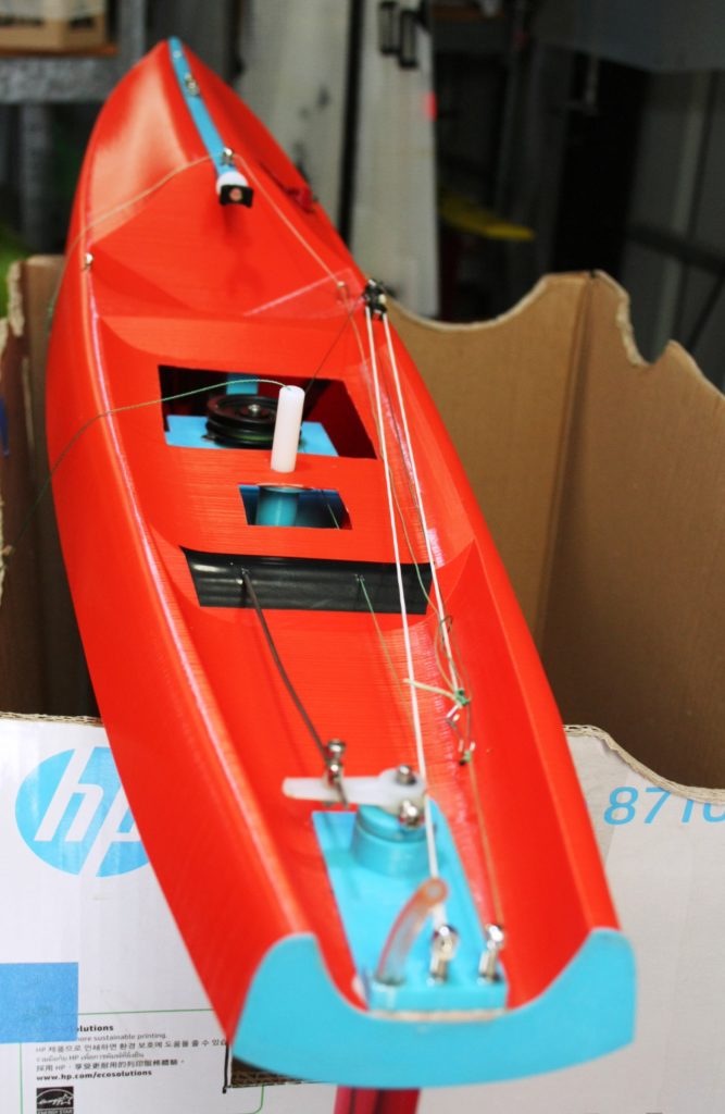
- Main pot size: 95x80mm (to allow the keel box to maneuvered and turned in there to put into place plus room for the waterproof servo and winch boxes)
- Battery pot size: 40x43mm (to allow the battery box to be epoxied to the hull… if that is where you want it)
- Receiver pot: 35x35mm (just big enough to get the receiver box in there)
- Wait until you have the keel installed before setting the rudder. This means you can install the rudder exactly parallel to the keel fin. Allow a slightly larger hole at the top of the deck to give you the option of lining up the rudder to the keel… however you do that, clamps etc.)
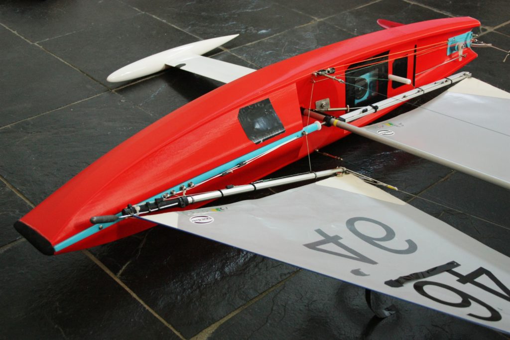
- When attaching eyelets and deck fittings, I run a few drops of epoxy into the hole before screwing/inserting the item. Any items with stress on the deck (ie sheet return) should have support underneath. The sheet layout I use is basic but but very effective and you can see this in the photographs. Again up to you.
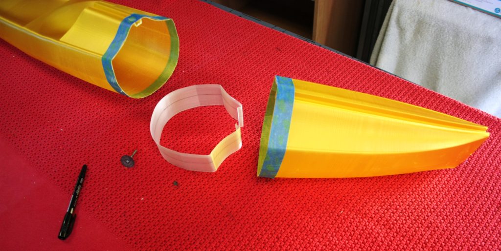
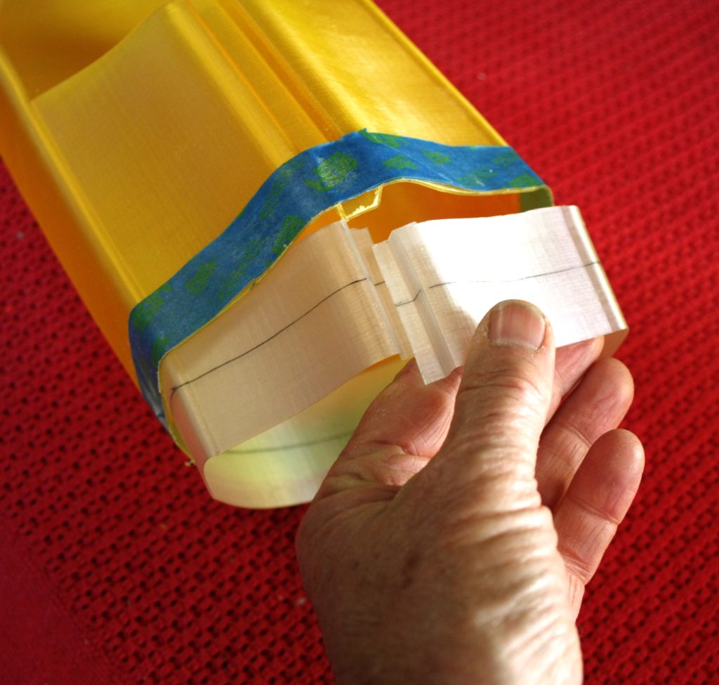
- Most will almost certainly be slicing and sleeving in some shape or form depending on the printer. I’ve added some images showing how to sleeve two sections together. The sleeve is made by printing a section of the hull (30-40mm wide) and then cutting a small slice out to allow it to fit neatly inside the two sections.
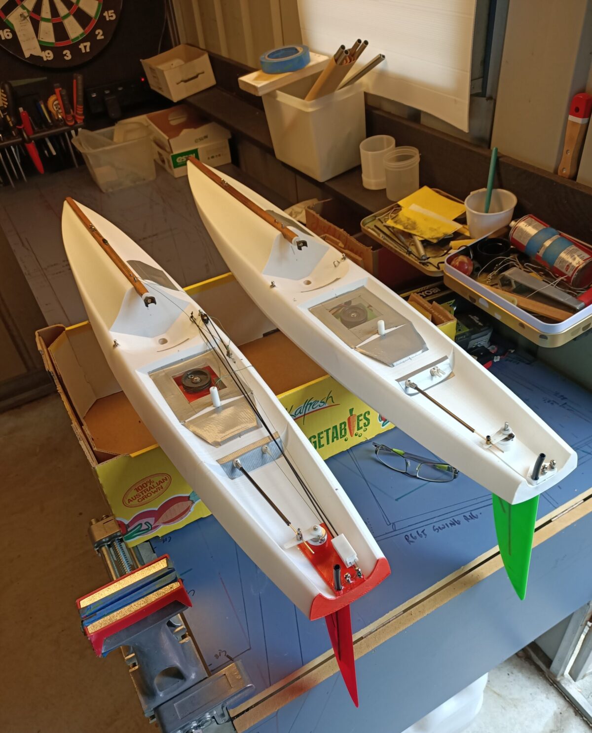
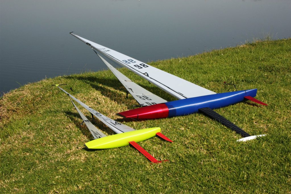
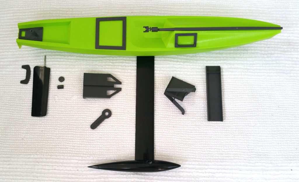
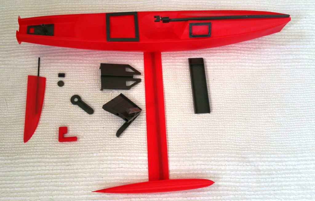
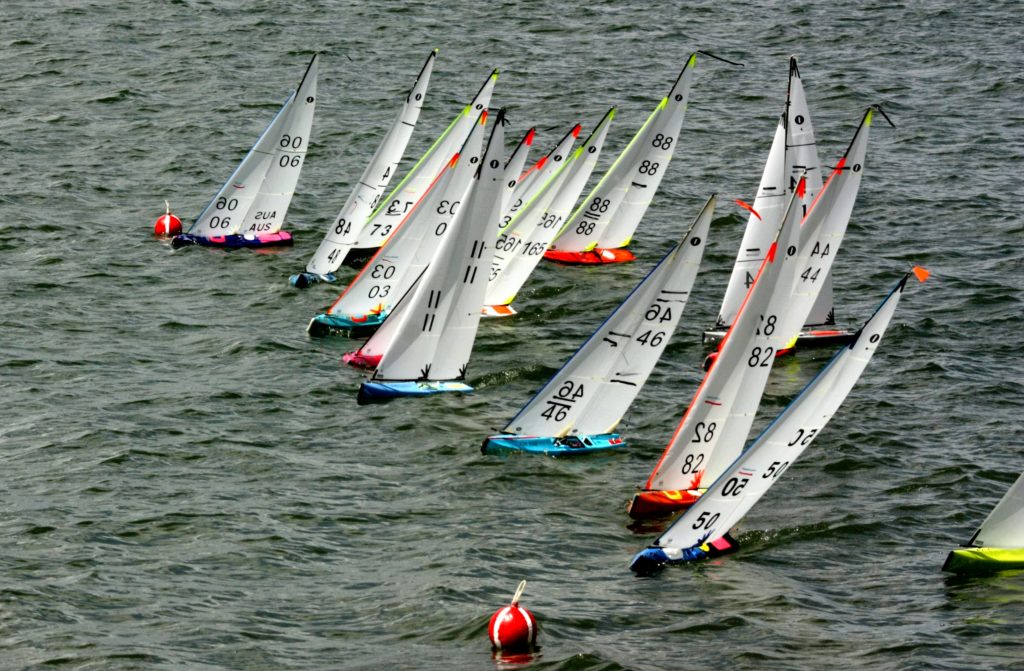
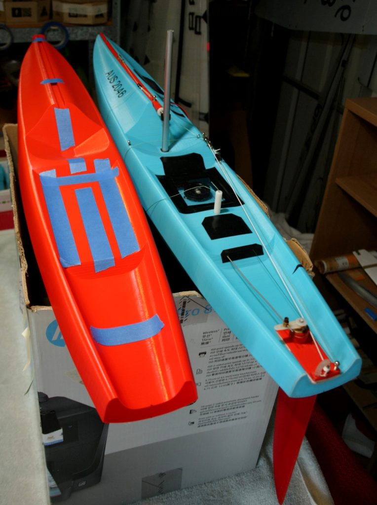
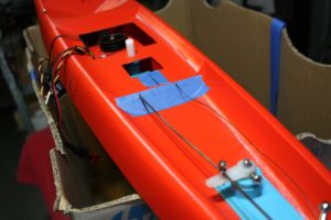
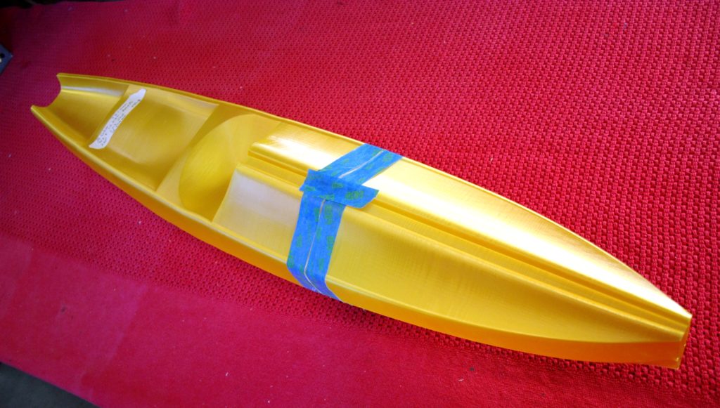
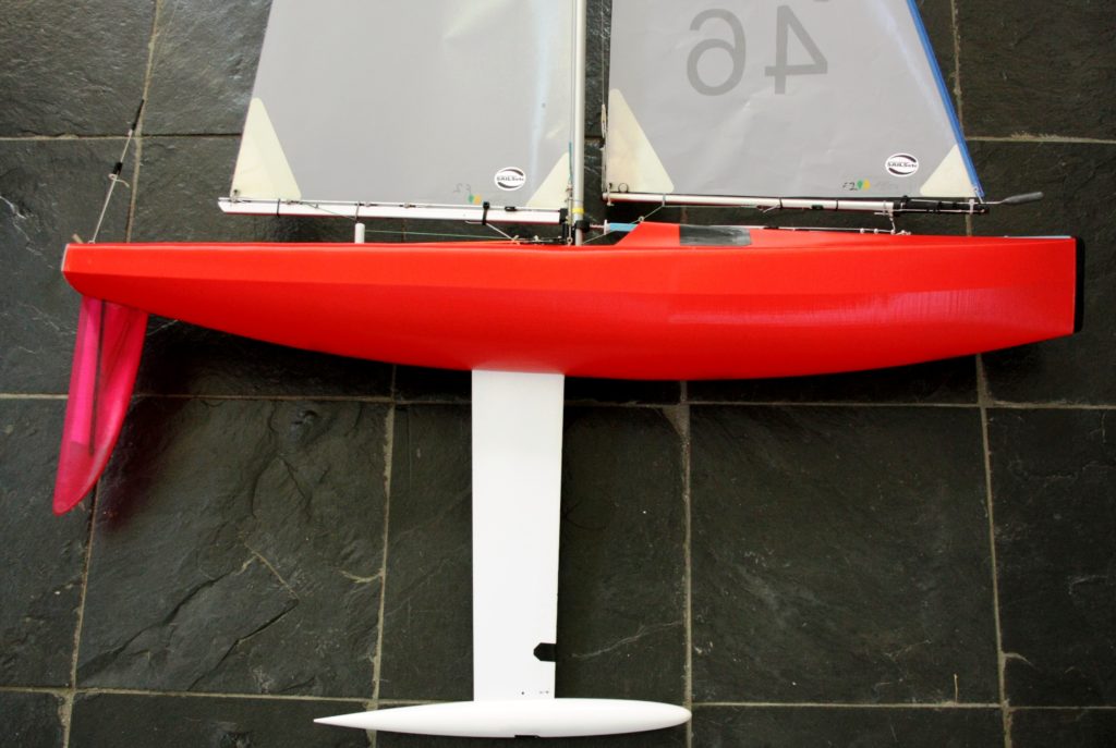
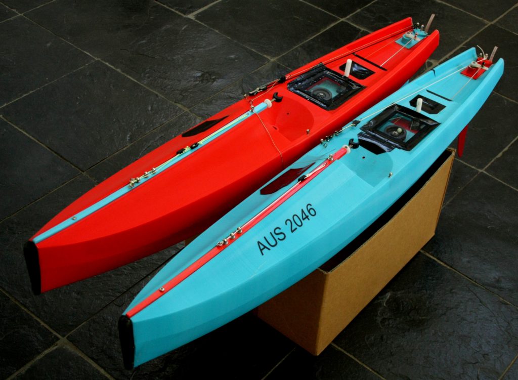
- Finally, the blue Sabre below is 160mm wide and the red Sabre is 170mm wide. I also have a 145 mm wide one. Which is the best? In waves and short chop, the wider ones appear to be better but in light air on flat water, the narrow one seems to be faster. The beauty of digital files is you can choose your width and dial it up on the 3d software. Let us know what you discover.
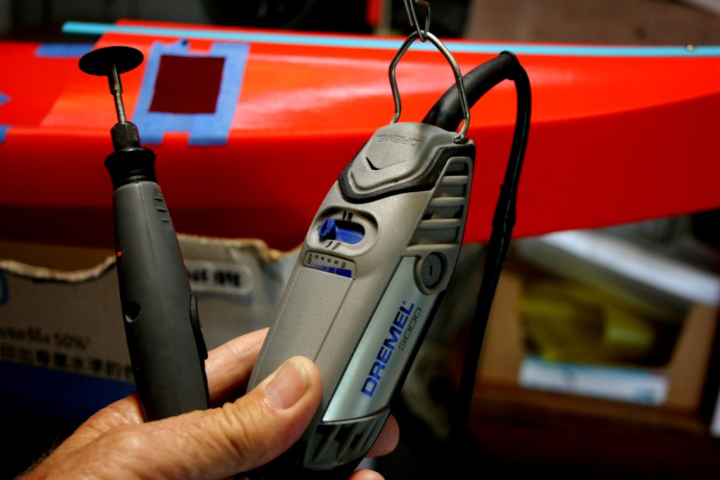
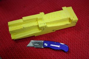
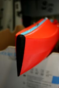
Before and After
Dremel cutting tools are worth their weight in gold. Remember to run the cutting tools and drills as slow as possible to stop melting the plastic. PLA+ cuts easier than normal PLA.
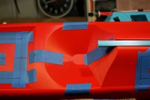
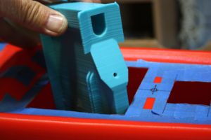
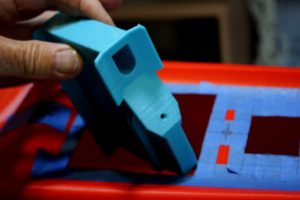
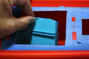
How to get the Keel Box in.
- Place a layer of epoxy on the hull floor ready for the base of the box
- Enter box down at an angle
- Slide into the hull
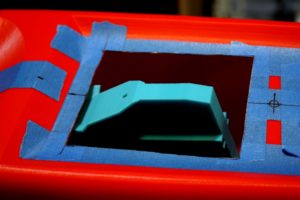
- Turn around
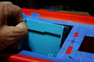
- Lift up into the position to slide forward
- Lift the deck carefully to allow the Keel Box to slide forward into place.
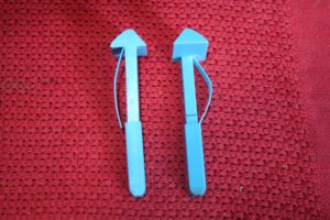
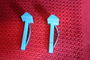
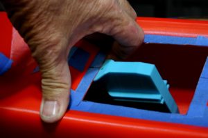
- Place the spring loaded struts into place at 45 degrees.
- Epoxy all in place
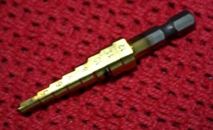
Multistep drills are very useful when creating holes on the deck
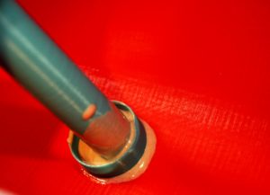
Sleeving is an easy and strong way to get sections connected. Simply print a section either side of where the join will be, then cut a small slice out to get it to fit inside the two sections. Alternatively, shrink the sleeve a tad until it fits neatly inside without cutting a slice. Finally, epoxy together.
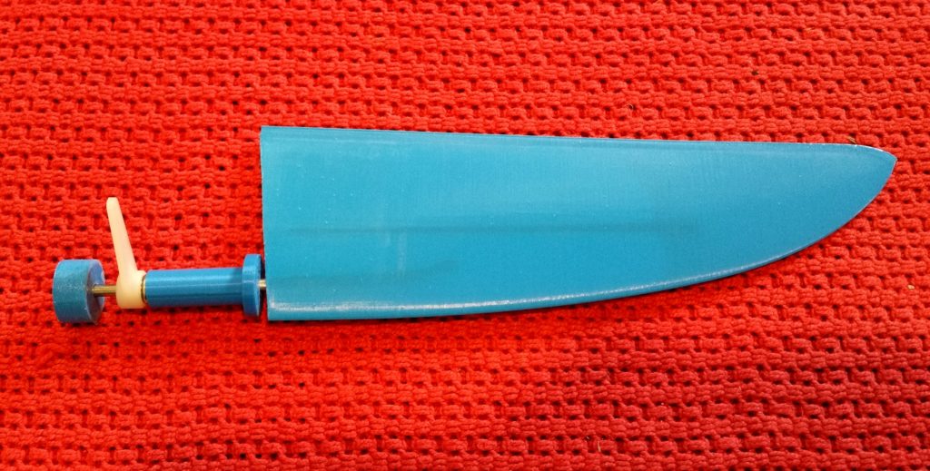
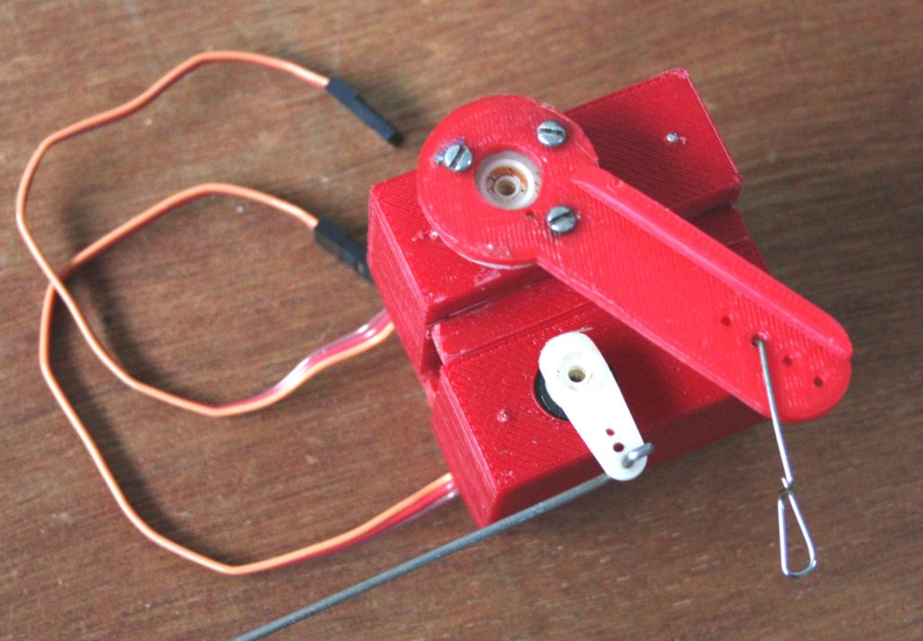
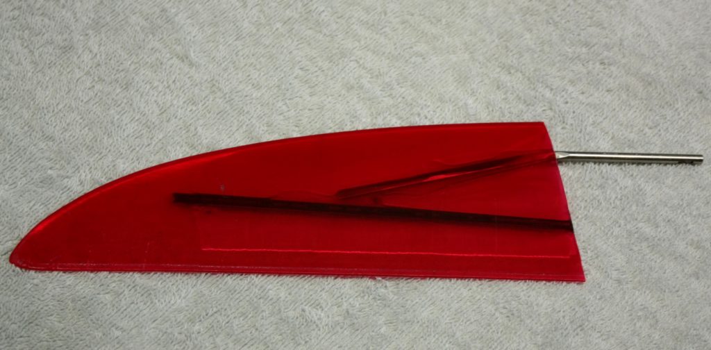
Making the rudder. This image shows the bent internal 4mm rod and the carbon tube insert to add to the stiffness. The rudder shell was formed using the single layer “spiral” mode.
The finished product.
Hull IOM BetaSabre V3 (Hagerup Holland)
Rudder shaft tube 4mm shaft v2 (Holland)
Rudder increase size to fit IOM (Hagerup Holland)
Keel case support strut lower section telescopic v1 (Holland)
Keel case support strut upper section telescopic v3 (Holland)
Glue pot v2 solid 20×10 mm (Holland)
Bow internal strut v3 fitted base and top (Holland)
Bow external strut v5 horizontal 461x8x10mm tapered (Holland)
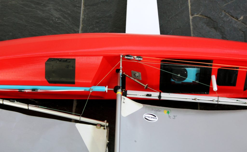
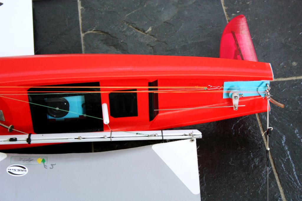
B. Detailed description of the pin, sheeting and deck layout
This description is for the IOM Sabre 3D. Just scale the process down for the smaller RC yachts.
First, if you haven’t please make sure you print with PLA+ from Esun. You should be able to secure a supplier either in country or internationally.
OK sizes for fittings. I use very basic layouts, and therefore rarely have things go wrong.
Front pin for A rig jib swivel depends on where your sivel is on the boom. The pin is 310mm from the front of the mast, this gives a small clearance to swing past the mast.
The sheet post is approximately 210mm behind the mast in the centre of the deck and set in a tube secured to the bottom of the hull.
The side stays are just behind the mast on the sides and and in line with the front edge of the keel. Please make sure you secure all pins with something solid below the deck… I glue three or four layers of PLA sheeting underneath with superglue if I can’t get the pin down through something solid like a strut. Drill a slightly undersized hole for the pins, test screw them in then remove and then drop a small amount of epoxy into the drill hole before finally securing them. Works well, nice and strong.
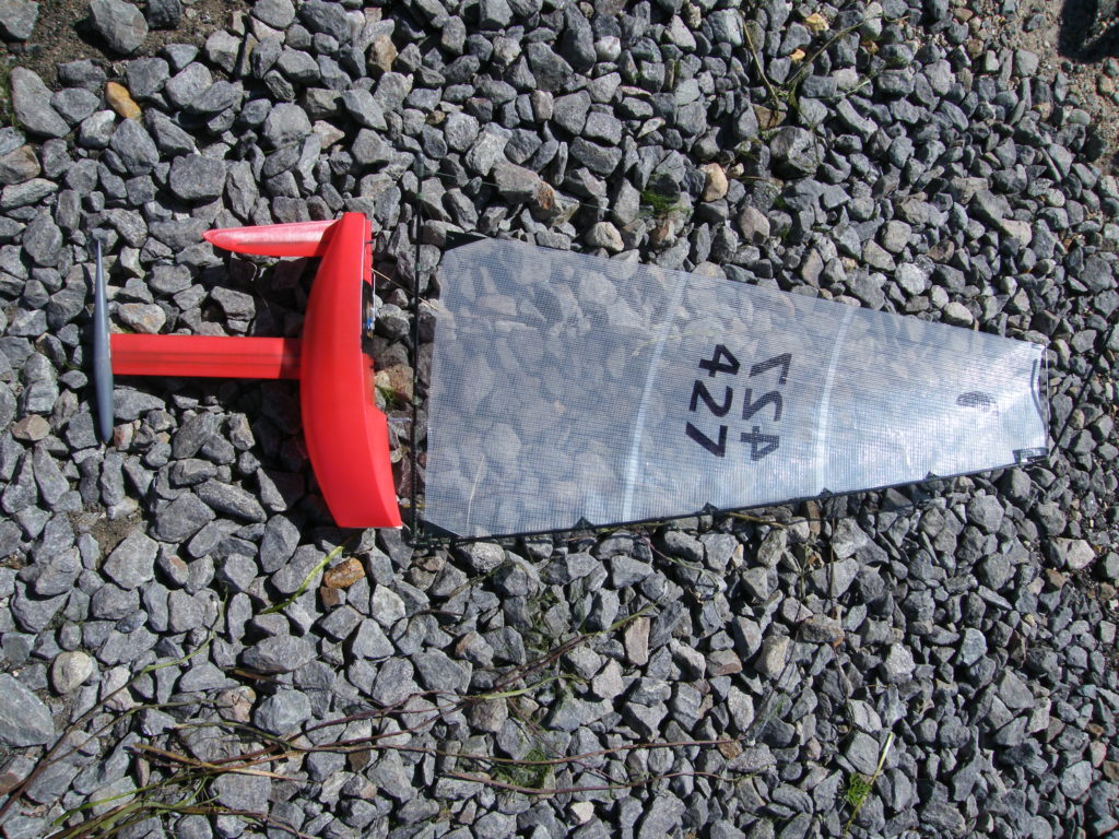
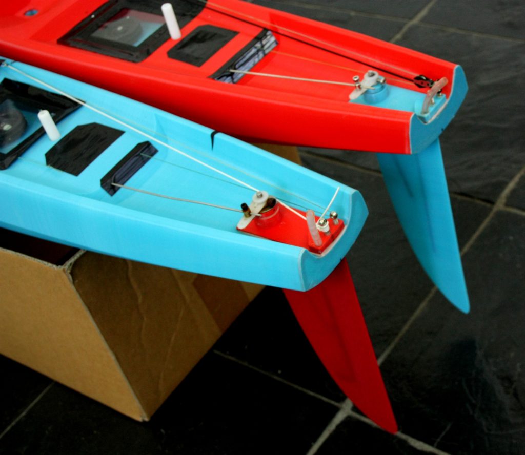
The rudder shaft is 55mm from the stern in the centre of course. Backstay pin is set in the backplate at the stern. The sheeting and rudder shaft are run out through the 45 degree bulkhead at the rear through deck and a sheet of sticky back or high quality insulation tape. The tight fit keeps it all water tight. They really do work, the trick is lining up the holes to set them straight through… good luck, a bit of thinking required there.
The sheeting is swivelled (returned) at the stern and starboard side stay. The side stay has two pulleys, one for the sheet and the other for the elastic for tensioning. This is a basic layout that works well and is mostly above deck to see if anything is going wrong.
Images attached below to help you visualise this.
That is the system I use for the Nano, RG65, 65 Class, IOM and 10R. The only differences are the dimensions.
Good luck and hope this helps.
C. Files from other 3d printing radio control enthusiasts.
Happy to host your special files here.