Why Not Start With A Racing Footy?
3d Printing for RC Yachts
Article 4
Selwyn Holland and Bill Hagerup
As part of the ongoing education of the RC Yachting community, Bill Hagerup and myself have been collaborating to close the loop for you, so to speak, so you can skip the design process and go directly to printing and building a very competitive Footy.
Bill has recently placed one of his very successful 3d printed Footy designs (hull, keel and rudder) on the web for download. This then allows me to tell you how to print it, and to finalise the process, Bill describes how to build the little guys to competition standard. So it is the old “one, two and three”.
The reality is, in terms of 3d printing if you can learn your trade on a smaller yacht then the leap to larger ones later is not really that much different. The challenges are not necessarily technical but more psychological and your belief in yourself.
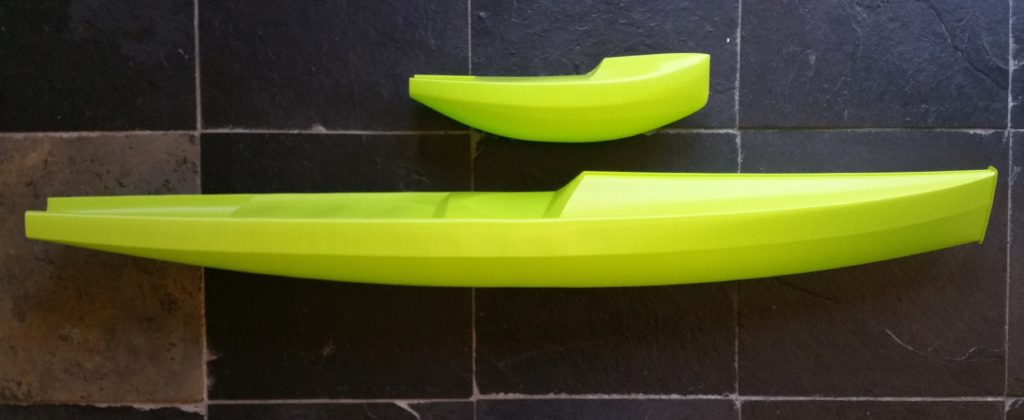
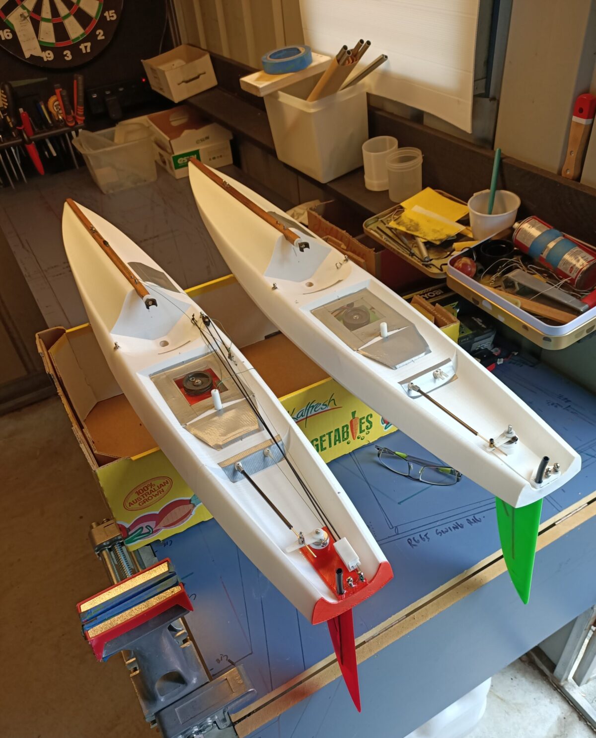
Image 1. Learn your craft with the Footy, then it is up to you if you wish to build bigger.
The steps in this process.
- You will need access to a good quality 3d printer and slicing program (Simpify 3d is highly recommended)
- Download the STL files from Thingiverse here: https://www.thingiverse.com/thing:2611611
- Read through this article and other helpful articles found on this page.
- Print the hull, keel and rudder.
- Read through the build instructions here: https://3dprintedradioyachts.com/exposed-bill-tells-construct-3d-printed-footy/
- Enjoy the delights of a racing Footy.
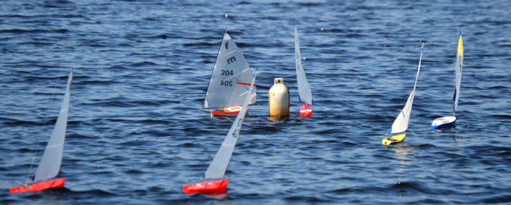
Image 2. Some of Bill’s delightful 3d Footies on the lake.
Some hints and tips to start
Just to quickly summaries a few things that have emerged from the many emails I have received concerning 3d printing. Without a doubt, the interest is rising rapidly and many are seeing what Bill and I saw in this technology just a mere 18 months ago.
Hint 1. Use PLA thermoplastic to learn with. Leave the other materials alone until you have mastered this very forgiving material. I will eventually write an article on what has been learnt about the other materials, but it is worth noting that I and my colleagues use PLA 100% of the time now for all the yacht hulls and parts.
Hint 2. Stay away from black PLA or really dark colours. They absorb infra-red much more rapidly and if left in the hot sun, like unpainted carbon fibre, can warp. This is not a good look when you are in the middle of a regatta. Always cover you yachts with a towel anyway.
Hint3. Carbon fibre infused PLA is not as rigid as normal PLA from my experience. So there is no advantage in using it at this stage.
Hint 4. Start with the printer’s standard settings, then test your way to success to find the “sweet spot”. As you change the settings, do so one at a time please. Remember the old science lessons around the scientific method? Control the variables and change only one thing at a time. The two big temptations are to speed up the printing to reduce the time and the other is to produce an “eggshell” hull. Believe me, slower in general produces a much finer surface result and a slightly thicker hull is more serviceable for building and racing with. From what Bill tells me, a 45g Footy hull is just as competitive but more resilient than an ultrathin 19g one. Yes, you can go that thin when you have found the sweet spot on your printer, but at some stage reality will win in your thinking.
Preparing the printer
The following is a set of steps I go through to make sure I have an excellent outcome. The printing is more of a spectator sport, the preparation is very important.
First. As mentioned, spend the time to find the sweet spot on your printer otherwise you will be throwing hulls in the bin in disappointment. Run short prints of say 2 inches (50mm) from the stern or bow changing one setting at a time.
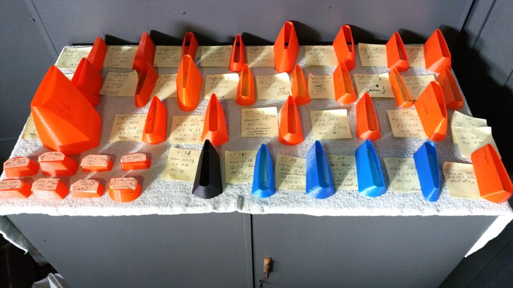
Image 3. Test test test (I did hundreds of tests which hopefully you will not have to do)
Secondly. Make sure your rails, wheels, bearings, trolleys, belts etc are all firm but not tight. Whatever the running gear on your printer, all should be moving smoothly with no “slack”, so to speak. The sweet spot means nothing if the head and nozzle are moving around outside the track during printing. This is another reason to not speed up the printing. Let it all happen quietly and get on with your life while the printer does its job. Also, make sure the printer is on a very firm base. A desk where other things are happening is a disaster waiting to happen. How do you think I know all this? My first printer was set up on my rather wobbly office desk and every time I worked at the laptop I would get funny lines on the print. It actually took me a while to wake up to what was causing the weird and irregular lines on the early hulls.
Third. The nozzle needs to be appropriate for the job. During the printing the nozzle is kept hot and the PLA melted and forced very accurately under slight pressure through the tiny hole in the nozzle. For Bill’s Footy hulls I use a 0.3 nozzle for the thinner hulls and 0.5 mm for the thicker ones. So a nozzle of around 0.4 using the “sweet spot” of your printer will service you well from my experience. Check that the starting point for the nozzle is just above the base surface. A good gauge is to slide a sheet of normal printing paper between the base and the nozzle. If the nozzle is too high then adhesion of the PLA to the surface is poor allowing the object to lift. If too close, the nozzle may damage the surface and the PLA can’t be extruded through the hole.
Finally. The initial preparation of the surface to help the thermoplastic stick is crucial. I have tried all sorts of surface preparations and have gone back to the simplest of all: a clean glass sheet and a glue stick smear over the place the PLA needs to stick to. I use a good quality flat paint scrapper to often scrap the surface clean. If you want a near perfect surface, then rub the surface with methylated spirits or water on a cloth. Most of the time I just scrap it clean and start the next job. The best glue stick for adhesion that I have found is the very commonly available Bostik Blu Stik found at most newsagents or office supplies.
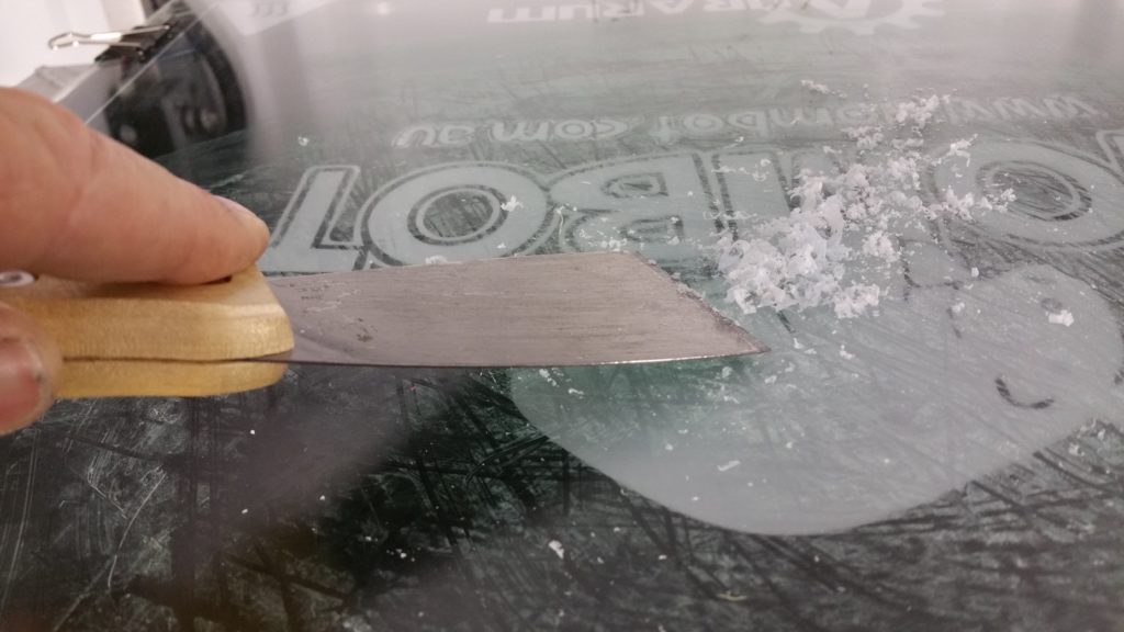
Image 4. Surface preparation is essential
Printing the hull
This is actually the easy part. You have done all the background preparations to make sure your printer is set up properly and you know the best settings, so let’s print.
Download the STL from Bill’s site in Thingiverse and import it into your favourite slicing program (like Simplify 3d). Orient the image on the platform so that there is a flat base attached to the platform. The Footy in this case can be printed from either the stern or the bow.
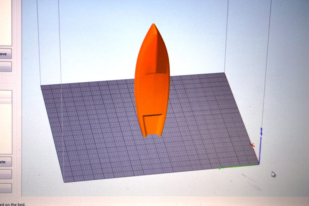
Image 5. Preparing the hull in “Simplify 3d”.
Just a word of warning, when doing other hull designs make sure that there is no surface less than 45 degrees to the horizontal. Otherwise, they will not print very well. Unless, of course, you have mastered “bridging”, but more on that in the future.
These are some essential settings for my style of printer but of course experiment with your own printer.
Nozzle; 0.4mm
Extrusion multiplier: 1.0 (standard starting point)
Extrusion width: 0.45
Primary layer height : 0.15 (too high and the layers do not bind well, causing cracking)
Top layer: 0 (can’t print over open space)
Bottom layer: 4 (to seal the base surface)
Shell layer: 1 (because you are using vase mode)
Vase mode: tick the box
Temperature: 195-205 degrees for PLA
Run the fans on the nozzle all the time if you can. Try to cool the PLA down quickly.
This should give you a strong, resilient hull with a race ready outside surface that needs no sanding or coating. Just construct and go racing, PLA is wonderful if left untouched on the outside.
Finally, prepare the file for printing. The slicer program converts to g-code, a set of instructions directing the printer on how to construct the object..
Load the g-code file into your printer. I tend to use a sim card to transfer information to the printer rather than rely on USB cables. Why? I was convinced by some experts early on that it was very good practice to get rid of the slight possibility that cables can “glitch”, especially annoying during the last hour of a 10 hour print job.
If you can’t do the full hull, then do the print in two sections and create a sleeve to join them. A very easy process described in one of the other articles on this page.
Don’t forget that Bill has published instructions at the same site on how to build a 3d Footy.
You should be able to take it from here. Printing the keel and rudder are basically the same process but you will need to take Bill’s advice on sizing the keel and rudder in the slice program before printing. Good table adhesion becomes more important the thinner the base of the object. So prepare well.
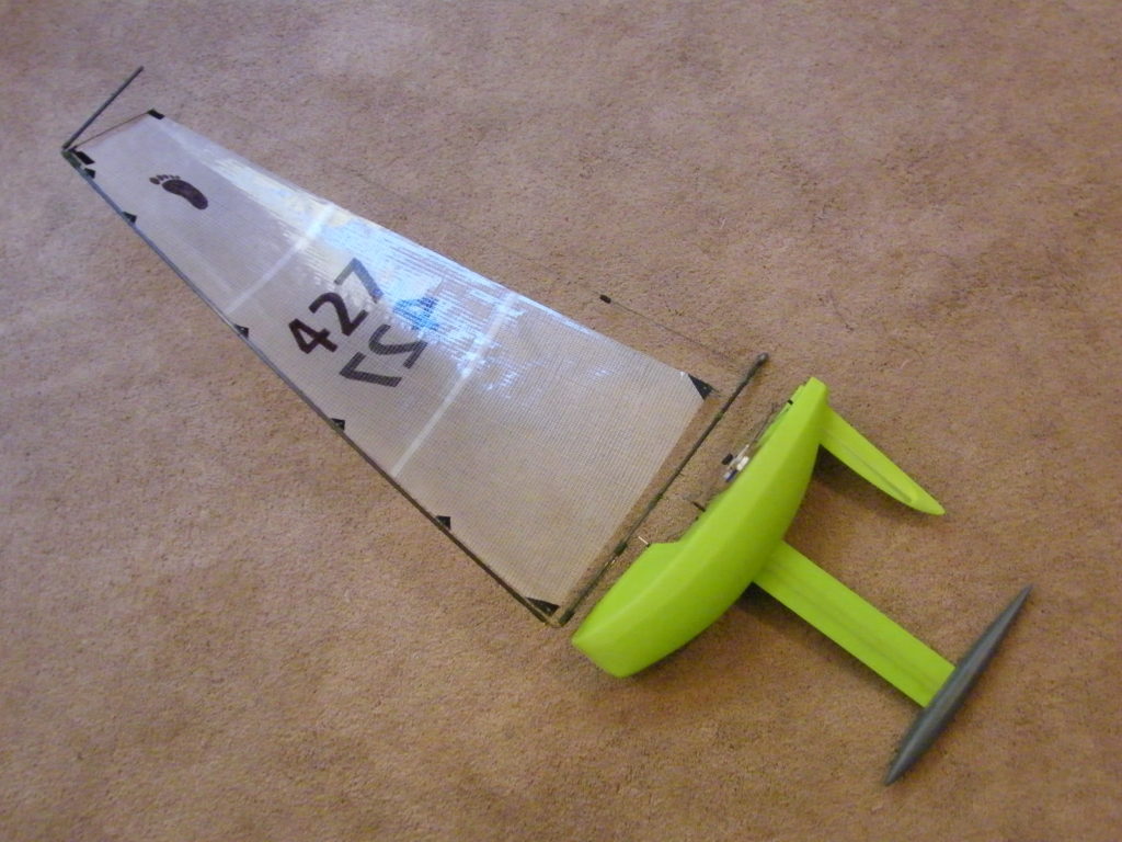
Image 6. This is what you are aiming for.
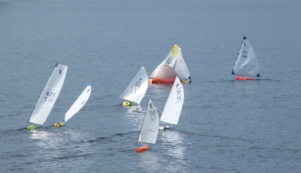
Image 7. And off racing
To summarise the print process
- Design a hull in your favourite drawing program (CAD) or download an STL file from a net site like Thingiverse.
- Load the STL file into your favourite free or purchased (Simplify3d) slicing program.
- Set your print parameters in this program. You may have to create multiple sections if the hull is too big or your printer is not big enough. No problem, just learn the sleeving process described in an earlier article or at the site mentioned above.
- Have the slice program convert the file to gcode so that the printer can read it and understand what needs to be done. Preferably save on a sim card or thumb drive to be inserted into the printer independent of the computer.
- Prepare your printer on the “sweet spot”, press the button and go to bed. It is always fun to wake up to something you have created on your own printer. I bet you don’t sleep in.
Good luck.
End of article.