3D Printing Article 3: How to design and print complex items for Radio Yachting
By Selwyn Holland,
Designs Bill Hagerup, images Selwyn Holland
Introduction
If I can assume that you now have at least a basic understanding of what 3D printing for our beautiful sport is all about, then this third article will make a lot more sense? If you are not sure of how 3D printing works at this stage, then I would encourage you to back track to the last two magazine issues and read through the first two introductory articles.
In this one I’m going to step it up a bit and show you some of the latest hulls and accessories that have been printed and lead you through the process of producing a basic skin that is strong, resilient and can be used to make light weight hulls.
These techniques will be mostly universal across all amateur machines both large and small regardless of the volume they can build. So, even at this stage, if you have a small low cost machine you should be able to produce lightweight hulls in small sections.
Some Breakthroughs
For some time now Bill Hagerup and I have been cooperating from opposite sides of the globe searching for the best techniques in 3D printing both in terms of the design side and materials to produce lovely fine, rigid and lightweight items including hulls. I will say it has been a very productive synergy between the two of us and many new “discoveries” have been made. We are hoping to share these breakthroughs with you all in this and future articles.

Image 1. Fully 3D printed Footy
This image neatly displays how far the process has proceeded. This was a package I recently posted to Bill (in the US) from Australia and included the following items:
- A 26g ultra lightweight hull, silky smooth surface, very rigid, strong and with a skin thickness of 0.37mm
- A 38g medium lightweight hull with identical qualities and skin thickness of 0.47mm
- Two bulbs of slightly different masses (now this was a big breakthrough)
- Two keels, stiff and thin with silky smooth finish.
- Special stern and bow inserts
For those who are obsessed with lightweight hulls I also produced one at 19g and this was also strong and rigid. But at this stage in the development and research I felt we should stay with the slightly thicker hulls until Bill has had time to trial them in his club events. For those who are not familiar with the Footy, I have been told that any hull under 50g is considered a lightweight one, so we were rather proud of achieving such low masses and maintaining strong hulls.
The bulbs I will discuss in future articles. They were an offshoot of the hull research that surprisingly showed that competitive and highly accurate bulbs can be produced overnight and without poisoning yourself with melted toxic lead.
The keels are also a surprise from the research, displaying outstanding stiffness when done properly. Imagine producing a new bulb and keel for your RG within a day or so… with you being completely in control of the parameters. Is your bulb a bit light? Why not print one overnight with an extra 50g in it?
Have I got your attention? More of that in future articles.
Today I Want To Talk To You About Hulls
Correct me if I am wrong here. Hulls take time, they are generally messy, often have to be done again, need lots of clean up and frustrating when the shape is not ideal. How many of you have simply caved in to buying a commercial hull because it is a known quantity and means you can go sailing quicker.
You may love fiddling with rigs and sails but leave the “big stuff” with the experts. How do I know this? My first yacht was a Graham Bantock Italico, second hand but fully set up and ready to race. Great let me at it, I had delusions of being a National Champion in the first year. But reality settled in and I realised my skill level needed more time, but in the meantime I quickly fell in love with the process of developing a boat from the hull up. Since then I’ve always bought hulls/keels/bulbs then worked on the rest myself.
By now, if you have been following these articles you should be starting to think that you can have a lot more control from the bulb to the crane if you want it. All without the need to develop the building skills of a master craftsman.
You see, the printing of a 3D hull is all about digital design and this can be changed in a few minutes of button pressing. I have often spotted something during a printing session, stopped the printer, made the adjustment and then redone the object. It is seriously that easy and that flexible.

Image 2: A raw hull being printed
Making The Basic Hull
There are two parallel methods that you can use to do this. I have wandered back and forwards between both and I think when it comes time for you to try, you will need to make up your own mind.
Hull Method A “The Shell”
- Start with the object in the CAD and when ready turn the solid object into a “shell”.
- Save as an STL file, then get the printer software to load the file
- In the printer software, the image has an inside and outside surface that has to be printed. I would suggest for a lightweight hull you select a single layer print inside and out with the infill mode turned off. The smaller the nozzle the thinner the layer but be careful you don’t get too thin, the surface may degrade. It is always a balance between reality and what you want.

Image 3. The Shell, notice the internal and external surface
Advantages include a nice solid hull with the two shells (internal and external) hanging on to each other, all assuming you get the temperatures and flow rate right. Also, for those who are adventurous in the CAD, you can change the thickness for various parts of the hull and internal fittings to get more strength or less mass when needed. But this is very advanced work and something to play with when you are happy with basic hulls.
Hull Method B “The Vase Method”
- Start with the solid object in the CAD
- Save the solid object as an STL file and then bring that file into the printing software
- You will now have a solid object to work with rather than a shell as in Method A.
- If your software can do this go to the “Vase” mode and select single layer printing. Turn off all other layering systems.
- This will produce a single layer that prints only the outside of the solid object. You may want to play with flow rate and nozzle sizes to get a great finish. Incorrect layering and not enough temperature or feed rate for the plastic creates poor adhesion and the hull will be brittle when you take it out of the machine. You will need to experiment, but worth it when you get it right.

Image 4 Single layer Vase Mode
Advantages include simplicity of building and speed of making the hull. It is worth persisting with to get it right. I mostly use this method for “skins” like hulls but use Method A for most other objects.
Variations in flow rate and nozzle sizes allow you to select everything from ultra ultra lightweight (19g Footy) to a very resilient and long term hull that is easier to work with when adding all the bits (38g Footy).
Handy Hint: Sleeving Hulls
Assuming your machine is not capable of long and full hulls, you will need to consider how to join the printed sections together. There are a number of effective ways of getting a near seamless and strong connection, but from my experience the sleeve process is the least difficult. This involves printing the same hull section across where your seam will be for about 2 cm either side. Cut a small strip off this sleeve long ways and this can then be rejoined but with a smaller diameter. With a bit of trial and error, this resized section will fit snugly inside the two hull sections you want to join, with enough overlap to grip and add strength when you epoxy them into place.
An interesting advantage is it adds some extra strength to ultra lightweight hulls if you are wanting to go that way.
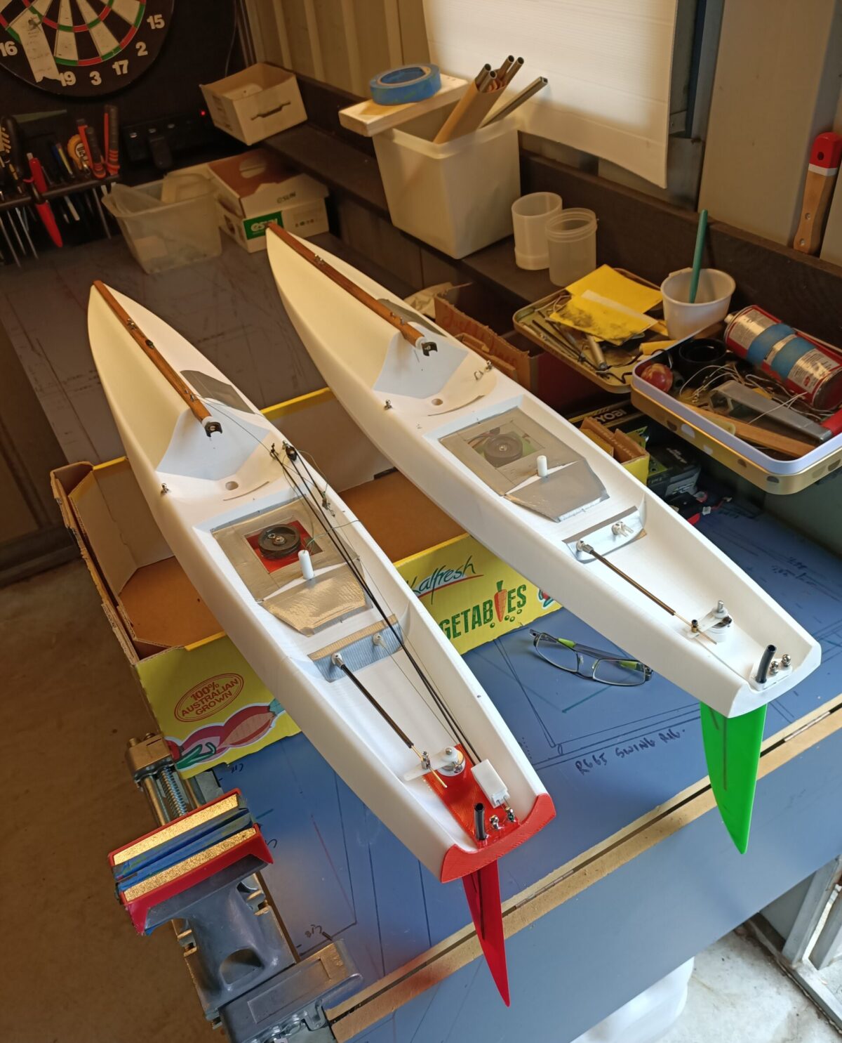
Stepping Up To An RG65 Hull
Scaling up to a bigger hull is fairly easy. If you are doing it in sections just learn to cut your hull up into an extra couple of lengths and sleeve them.
This is one of Bill’sRG65 designs and it came out with a very nice finish, lightweight (82g) and a hull thickness of 0.42 mm. It could go even lighter and if you want to make it slightly wider with a deeper rocker… it is only a few strokes of the buttons and a bit of time in the machine. The flexibility of this technology is astounding and all within the reach of anyone willing to learn a few new tricks.

Image 5 RG65 Raw from the printer at 82g and 0.42mm thickness.
Enjoy the journey
Future Articles
I’m intending to produce these articles in the next couple of issues.
Article 4. Producing specialist items like keels
Article 5. Understanding the settings on 3D printers.
End of article